Cold shrink assembly

a technology of assembly and cold shrinking, which is applied in the direction of electric cable installation, cable junction, insulation body, etc., can solve the problems of difficult unwinding and removal of plastic core, difficult to take apart such a device, and often stuck pull cord inside the spli

Active Publication Date: 2015-12-01
THOMAS & BETTS INT INC
View PDF49 Cites 15 Cited by
  • Summary
  • Abstract
  • Description
  • Claims
  • Application Information

AI Technical Summary

Problems solved by technology

One drawback with such cold shrink products is that the pull cord often gets stuck inside the splice.
As a result, it is often difficult to unwind and remove the plastic core to properly insulate the wires / splice.
Taking apart such a device may be time consuming and difficult in certain circumstances.

Method used


Image

  • Cold shrink assembly
  • Cold shrink assembly
  • Cold shrink assembly

Examples


Embodiment Construction

[0012]The following detailed description refers to the accompanying drawings. The same reference numbers in different drawings may identify the same or similar elements. Also, the following detailed description does not limit the invention.

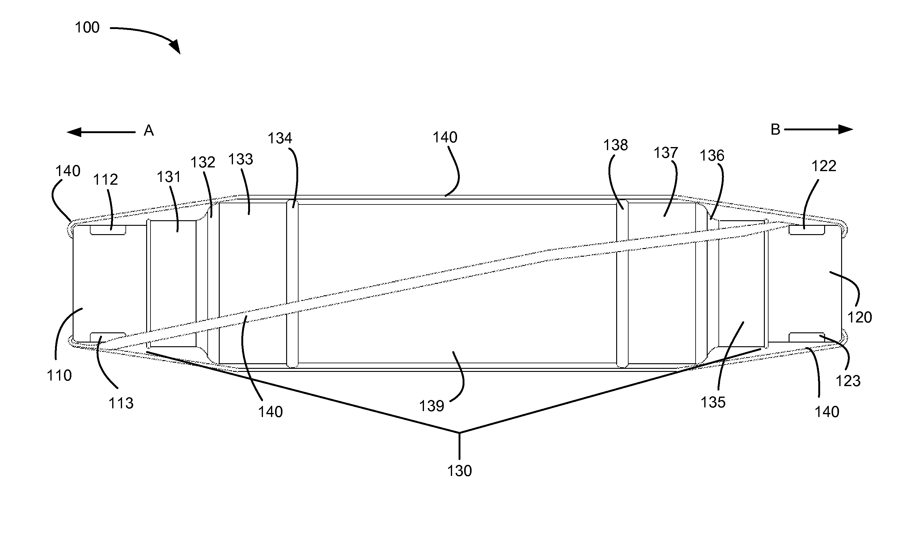
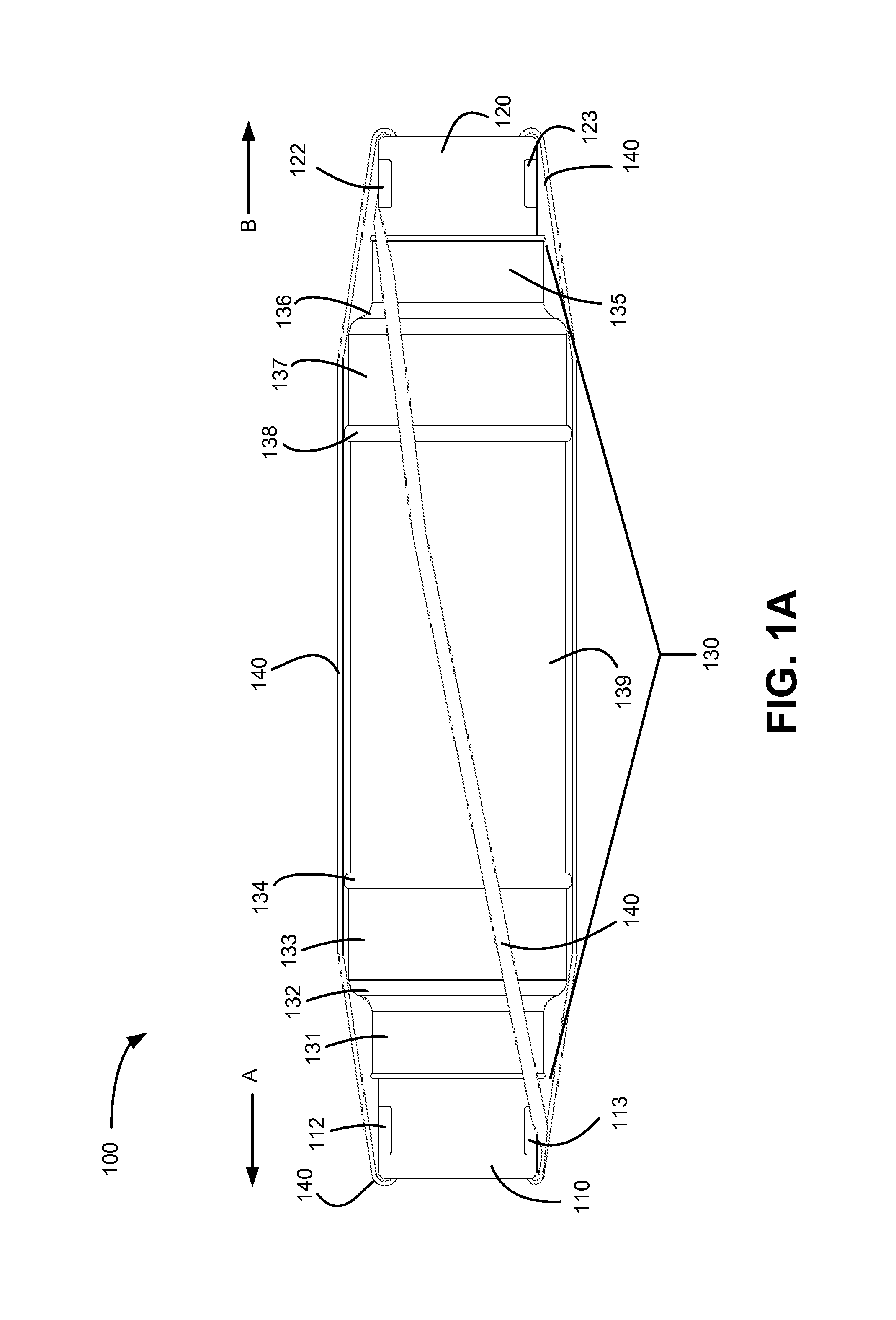
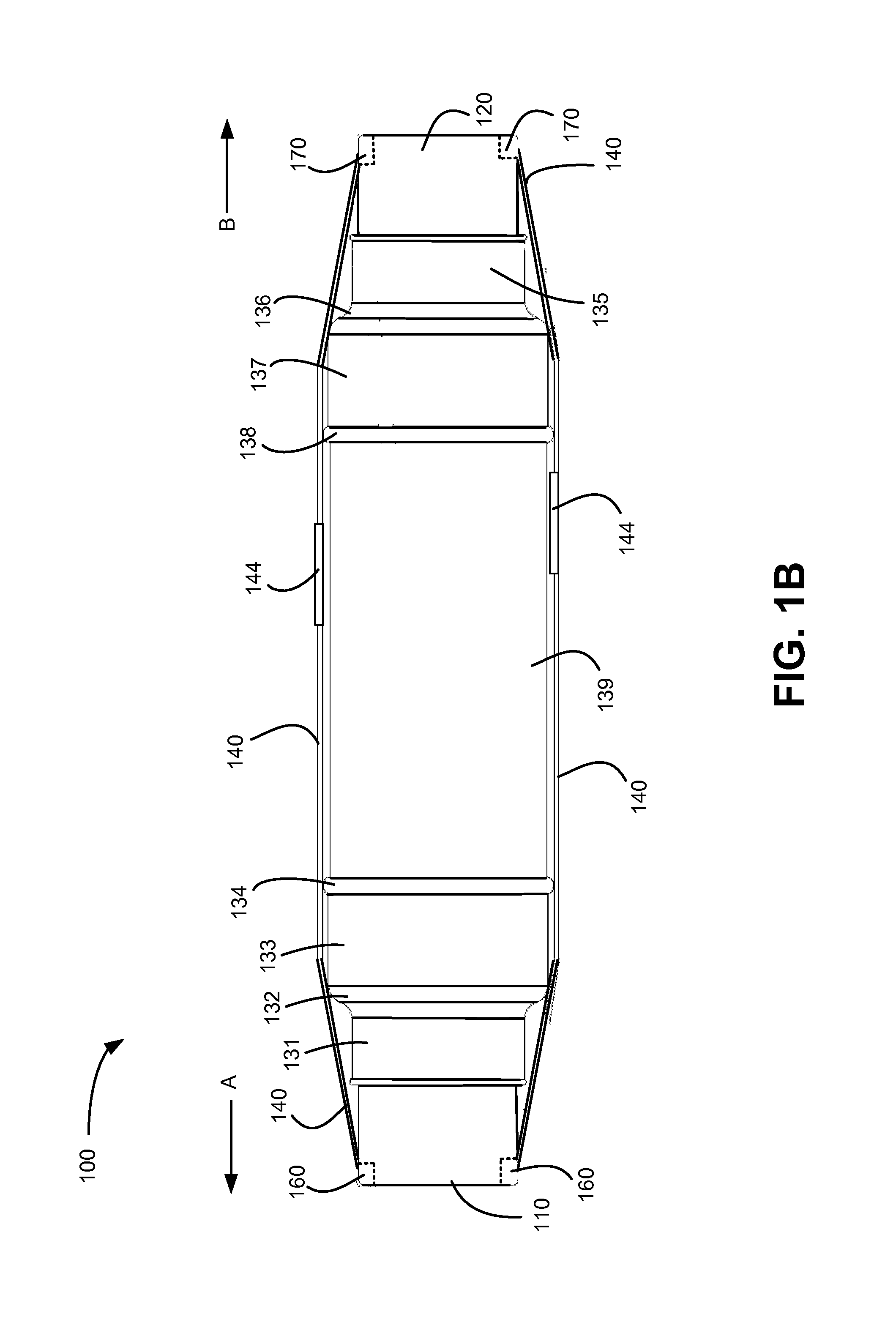
[0013]Embodiments described herein provide a cold shrink assembly that may be used to install electrical insulation over electrical wires or a splice. In an exemplary implementation, the cold shrink assembly may include two cores upon which a cold shrink material is placed. The two cores may be made of multiple portions that make up each of the two cores. When the cold shrink material is placed over the cores, the pressure exerted by the cold shrink material on the cores causes the cores to begin to push out from each other. A band or strap is then placed over the cores to hold them in the desired position. When the cold shrink material is ready to be installed, the cores are placed (e.g., slid) onto an electrical cable and moved to a location at ...


PUM

PropertyMeasurementUnit
distanceaaaaaaaaaa
distanceaaaaaaaaaa
distanceaaaaaaaaaa

Abstract

A cold shrink assembly includes a first member, a second member, a shrink fit joint and a band. The first member has a tapered shape and includes a first opening or first notch. The second member has a tapered shape and includes a second opening or second notch. The shrink fit joint is disposed over a portion of the first and second members. The band is configured to secure the first and second members in a predetermined position. The band extends through the first opening or first notch, along a first portion of an outer surface of the cold shrink assembly, through the second opening or second notch, and loops back to the first opening or first notch along a second portion of the outer surface of the cold shrink assembly.

Description

RELATED APPLCATION[0001]This application claims priority under 35 U.S.C. §119 based on U.S. Provisional Patent Application No. 61 / 707,298, filed Sep. 28, 2012, the disclosure of which is hereby incorporated herein by reference.BACKGROUND INFORMATION[0002]Cold shrink products are typically used to insulate electrical wires and / or electrical splices. For example, one conventional cold shrink product includes a plastic core, a pull tab and insulating material formed over the plastic core. An installer may slide the plastic core over an electrical cable to the location of the splice and pull the pull tab to unwind the plastic core. The insulating material then contracts over the electrical wires / splice. One drawback with such cold shrink products is that the pull cord often gets stuck inside the splice. As a result, it is often difficult to unwind and remove the plastic core to properly insulate the wires / splice.[0003]Another conventional cold shrink product includes a plastic tube that...

Claims


Application Information

Patent Timeline
Patent Type & Authority Patents(United States)
IPC IPC(8): H01B17/58H01H19/00H02G15/18H01B19/00
CPCH01B17/58H02G15/1826H01B19/00Y10T29/49227H02G1/14
Inventor HERNANDEZ, CARLOSSZYSZKO, STANLEY S.LUCERO, ROGER L.GARDNER, DANIEL L.
Owner THOMAS & BETTS INT INC
Why Eureka
Try Eureka