Packet conflict resolution

Active Publication Date: 2015-12-01
NICIRA
View PDF3 Cites 26 Cited by
  • Summary
  • Abstract
  • Description
  • Claims
  • Application Information

AI Technical Summary

Problems solved by technology

While the translated source port number is randomly selected and therefore will generally be different even if two separate distributed SNAT elements select the same IP address, in some cases the SNAT elements will choose the same source IP address and port number, thereby creating a conflict if the transport protocol and destination IP address and port number are the same.

Method used


Image

  • Packet conflict resolution
  • Packet conflict resolution
  • Packet conflict resolution

Examples


Embodiment Construction

[0031]In the following detailed description of the invention, numerous details, examples, and embodiments of the invention are set forth and described. However, it will be clear and apparent to one skilled in the art that the invention is not limited to the embodiments set forth and that the invention may be practiced without some of the specific details and examples discussed.

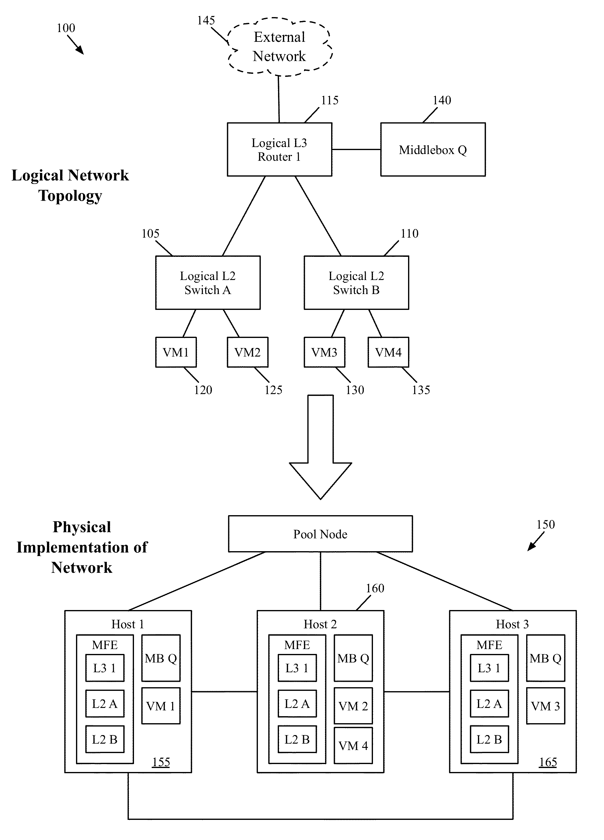
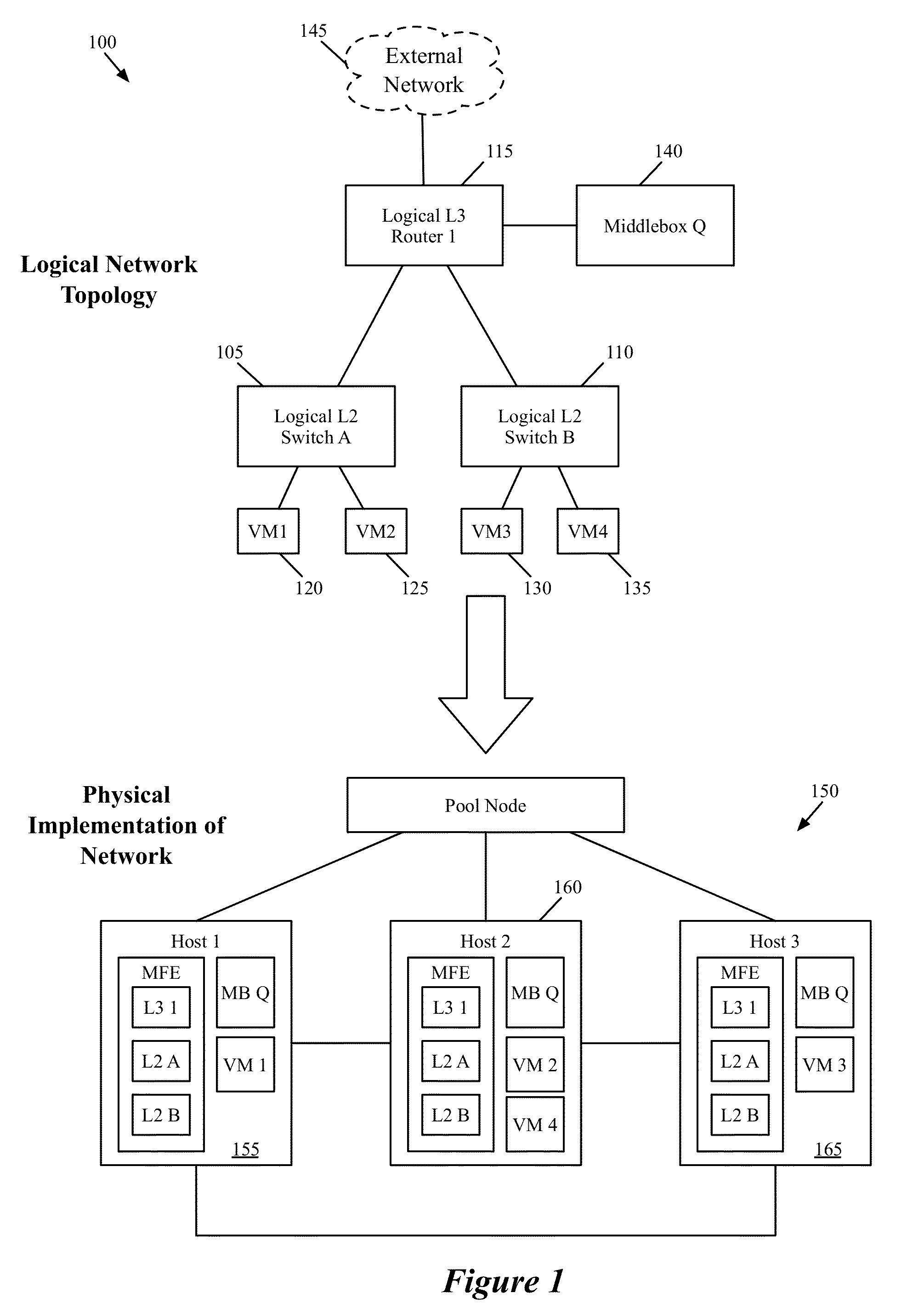
[0032]Some embodiments provide novel packet processing techniques within a managed network that enable first-hop processing of bi-directional stateful traffic that passes through distributed middleboxes (e.g., firewalls, load balancers, network address translators, etc.). In order to enable such traffic, some embodiments dynamically generate flow entries at one end of a connection between two managed forwarding elements. These dynamically-generated flow entries (i) resolve conflicts between two separate connections that have similar or identical connection identification data and (ii) automatically forward rev...


PUM


Abstract

Some embodiments provide a method for a first managed forwarding element that implements a logical network. The method receives a packet from a second managed forwarding element. The first packet has an initial set of characteristics defining a first connection between a source machine connected to the second managed forwarding element and a destination machine connected to the first managed forwarding element. The method determines whether a second connection exists with the initial set of characteristics between a different machine connected to a third managed forwarding element and the destination machine. When a second connection exists with the initial set of characteristics, the method modifies at least one characteristic of the packet such that the modified packet does not have the same set of characteristics. The method delivers the modified packet to the destination machine.

Description

CLAIM OF BENEFIT TO PRIOR APPLICATIONS[0001]This application is a continuation-in-part of U.S. patent application Ser. No. 13 / 678,518, now published as U.S. Publication 2013 / 0128891, filed Nov. 15, 2012. Application Ser. No. 13 / 678,518 claims priority from U.S. Provisional Application 61 / 560,279, filed Nov. 15, 2011. This application is also a continuation-in-part of U.S. patent application Ser. No. 13 / 678,522, now published as U.S. Publication 2013 / 0132532, filed Nov. 15, 2012. Application Ser. No. 13 / 678,522 claims priority from U.S. Provisional Application 61 / 560,279, filed Nov. 15, 2011. This application is also a continuation-in-part of U.S. patent application Ser. No. 13 / 589,074, now published as U.S. Publication 2013 / 0051399, filed Aug. 17, 2012. Application Ser. No. 13 / 589,074 claims priority from U.S. Provisional Application 61 / 666,876, filed Jul. 1, 2012; U.S. Provisional Application 61 / 654,121, filed Jun. 1, 2012; U.S. Provisional Application 61 / 643,339, filed May 6, 2012...

Claims


Application Information

Patent Timeline
Patent Type & Authority Patents(United States)
IPC IPC(8): H04L12/24H04L12/931G06F11/07
CPCH04L41/0896H04L49/70G06F11/07H04L61/2535H04L45/54H04L41/0895H04L61/251
Inventor KOPONEN, TEEMUZHANG, RONGHUA
Owner NICIRA
Why Eureka
Try Eureka