Underwater sensor network routing method based on multiple underwater autonomous vehicles

An autonomous vehicle and underwater sensor technology, which is applied to services, data exchange networks, and transmission systems based on specific environments, and can solve information redundancy, data packet transmission delays, and nodes that cannot find the next hop forwarding node. and other problems, to achieve the effect of improving network transmission performance, reducing energy consumption, and avoiding data packet conflicts.

Active Publication Date: 2019-05-17
TIANJIN CHENGJIAN UNIV
View PDF5 Cites 15 Cited by
  • Summary
  • Abstract
  • Description
  • Claims
  • Application Information

AI Technical Summary

Problems solved by technology

The DBR protocol has good performance in a dense network, but in a sparse network, multiple forwarding nodes may transmit the same data packet, or the node cannot find a suitable next-hop forwarding node, resulting in information redundancy Sending and transmission delay of packets
The REBAR (Reliable and Energy Balanced Routing Algorithm) routing protocol invented by Chen J et al. proposes node mobility as a positive factor for balancing network energy consumption, which divides the network into two areas and defines one of them as the hotspot area around the convergence , and the other parts are common areas. The protocol will exchange the nodes in the two areas through the mobility of nodes, so as to balance the energy consumption between each node. However, this protocol needs to know the geographical location of each common node and the s

Method used


Image

  • Underwater sensor network routing method based on multiple underwater autonomous vehicles
  • Underwater sensor network routing method based on multiple underwater autonomous vehicles
  • Underwater sensor network routing method based on multiple underwater autonomous vehicles

Examples


Embodiment Construction

[0043] The present invention will be described in detail below in conjunction with the accompanying drawings and specific embodiments.

[0044] Such as Figure 4 As shown, the underwater sensor network routing method based on multiple underwater autonomous vehicles provided by the present invention includes the following steps carried out in order:

[0045] Step 1. Network initialization phase:

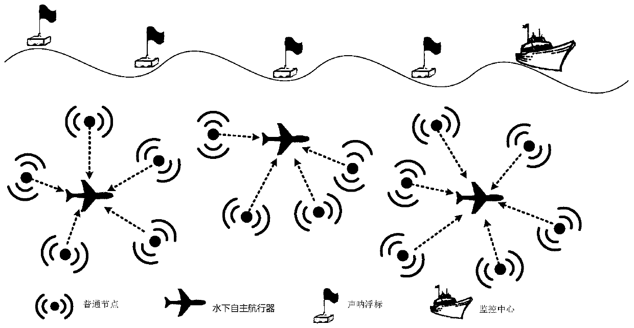
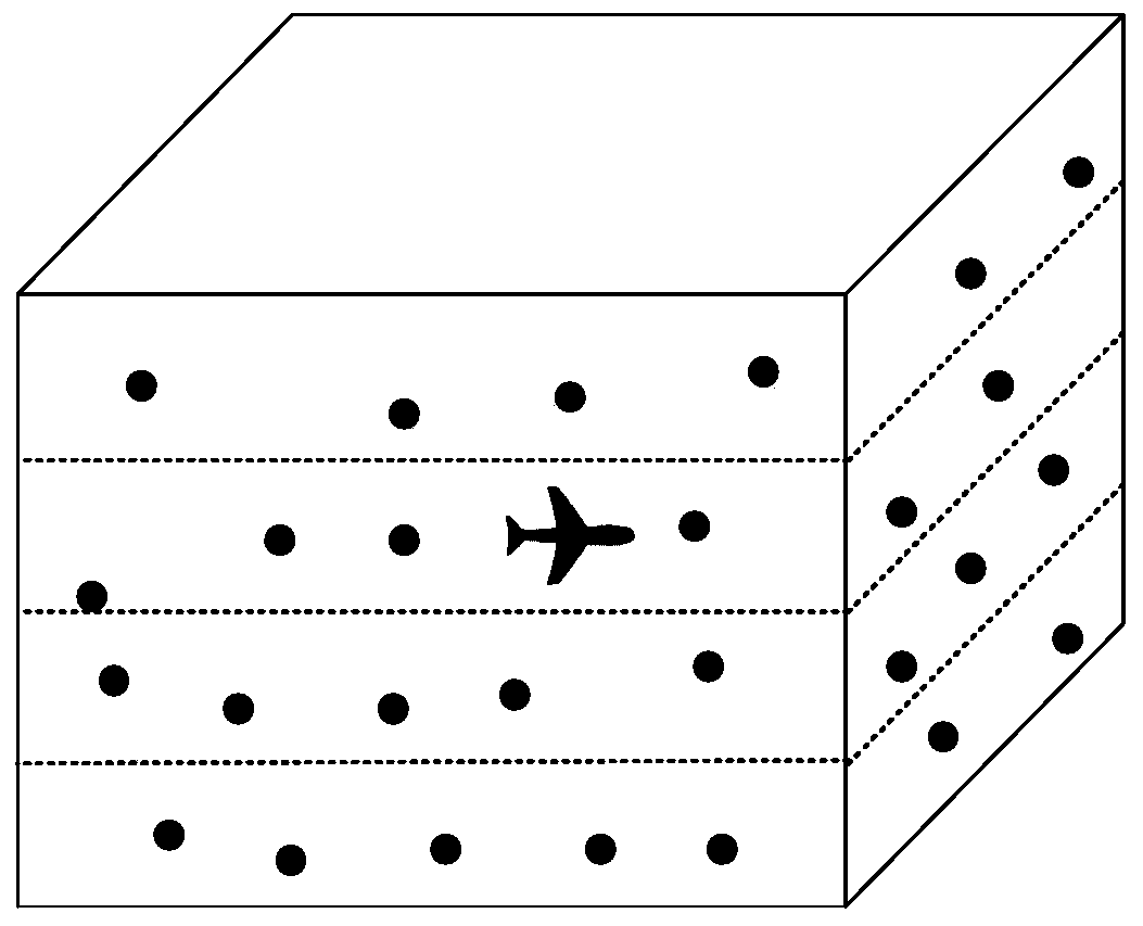
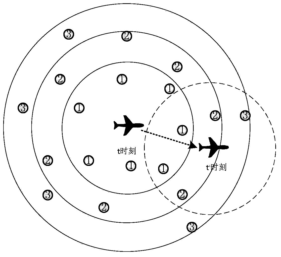
[0046] Step 1.1: Build as figure 1 The underwater sensor network model based on multiple underwater autonomous vehicles is shown, each underwater autonomous vehicle is used as a converging node, and the layered distance threshold D is set, the information collected by the underwater autonomous vehicles is expressed as a data packet The form broadcasts to each common underwater sensor node, and the broadcast information includes the transmission power of the underwater autonomous vehicle;

[0047] Step 1.2: After receiving the broadcast information, each common underwater sensor nod...


PUM


Abstract

The invention discloses an underwater sensor network routing method based on multiple underwater autonomous vehicles. The method comprises the steps of network initialization, data transmission, network restoration and the like. In the network initialization stage, a dynamic network hierarchical structure is constructed; the underwater common sensor nodes in the underwater sensor network are layered, so that a progressive gradient is formed, and a data packet can be transmitted to a corresponding underwater autonomous vehicle according to the hierarchical relationship of the underwater commonsensor nodes in a subsequent data transmission stage. In the data transmission stage, the underwater common sensor node sorts the transmission priorities of the candidate nodes according to the composite forwarding factors of the candidate nodes, and transmission coordination of the candidate node set is carried out based on the transmission priorities of the candidate nodes, so that data packet conflicts are avoided, and the network delay is reduced; in the network restoration stage, the network restoration model is utilized to carry out periodic restoration when the initial dynamic network hierarchical structure changes, so that the transmission performance of the underwater sensor network is improved.

Description

technical field [0001] The invention belongs to the technical field of underwater wireless sensor networks, in particular to an underwater sensor network routing method based on multiple underwater autonomous vehicles. Background technique [0002] Underwater sensor network is an important application of wireless sensor network under water. The underwater sensor network refers to the deployment of underwater sensor nodes with low energy consumption and a certain communication distance in the designated sea area, and the network is automatically established by using the self-organization ability of the nodes. These underwater sensor nodes have acoustic communication capabilities, while the sonobuoys floating on the surface have video and acoustic communication capabilities. The underwater sensor node transmits the acoustic signal to the sonobuoy on the water surface. After the sonobuoy receives it, it transmits it to the control center through the radio frequency signal, and...

Claims


Application Information

Patent Timeline
IPC IPC(8): H04W4/38H04W40/08H04W40/10H04W40/12H04W40/20H04L12/733H04L12/725H04L12/721H04L45/122
Inventor 李成丁钰莹郝琨赵璐
Owner TIANJIN CHENGJIAN UNIV
Why Eureka
Try Eureka