
Radio transmission device and retransmission control method

Inactive Publication Date: 2011-05-19
PANASONIC CORP
View PDF8 Cites 15 Cited by
  • Summary
  • Abstract
  • Description
  • Claims
  • Application Information

AI Technical Summary

Benefits of technology

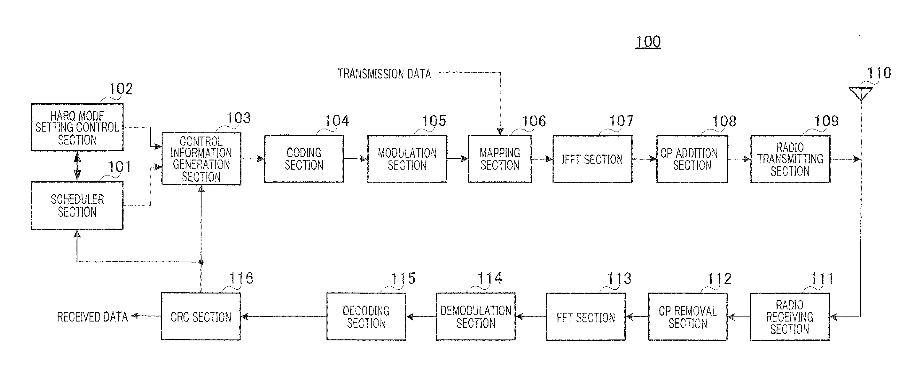
[0018]According to the present invention, with radio resources for adopting asynchronous HARQ, it is possible to switch to asynchronous HARQ without reporting control information expressly per mobile station, so that switching errors from synchronous HARQ to asynchronous HARQ accompanied by reception errors of allocation information do not occur. Therefore, according to the present invention, it is possible to reduce the amount of radio resources for allocation information allocated to an excessive degree and the rate of collisions between transmission packets. Consequently, according to the present invention, it is possible to reduce the amount of radio resource consumption required for signaling needed to report band allocation information and HARQ operation modes and reduce the rate of collisions between transmission packets accompanied by reception errors of band allocation information.

Problems solved by technology

Particularly, in a system using a single carrier method including SC-FDMA (Single Carrier FDMA) and CDMA-FDMA, continuous bands need to be allocated to one packet, and therefore, when resource fragmentation occurs, large continuous bands cannot be allocated to one mobile station, causing a significant decrease in peak data rate and making scheduling difficult.
However, in a system adopting the above synchronous non-adaptive HARQ and persistent scheduling at the same time, a case where a collision occurs between a retransmission packet by synchronous non-adaptive HARQ and the initial transmission packet by persistent scheduling.

Method used


Image

  • Radio transmission device and retransmission control method
  • Radio transmission device and retransmission control method
  • Radio transmission device and retransmission control method

Examples


case b

[0065](Case B) where another packet with priority (e.g. a packet subject to persistent scheduling) is allocated to predetermined allocation radio resources.

case c

[0066](Case C) where continuous and relatively wideband resources are secured, that is, where resource fragmentation is canceled.

[0067]FIG. 4 shows an example of relationships between radio resource positions (i.e. sub-frames) and rates of producing allocation information about cases (cases A, B and C) where a retransmission is performed using the allocation information.

[0068]Among these cases, in case A, allocation information is produced depending on the location and the mobility of a mobile station, so that, generally, allocation information is produced over radio resources uniformly. Accordingly, it is difficult to predict radio resource positions (i.e. sub-frames and RBs) in which adaptive HARQ using allocation information is performed, in advance.

[0069]Next, case B often occurs at sub-frames to which radio resources for the initial transmission in persistent scheduling are allocated.

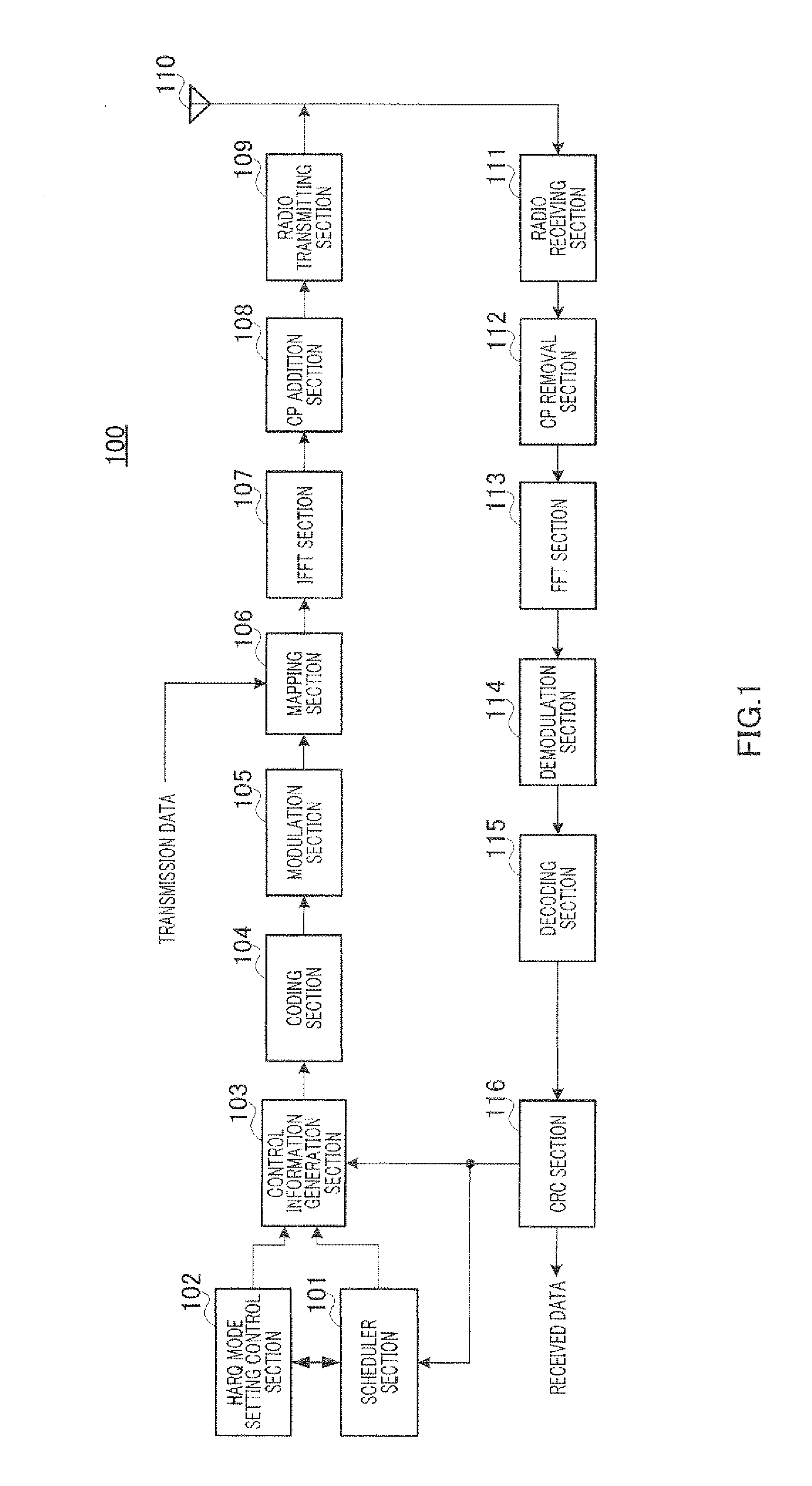
[0070]Scheduler section 101 in the base station is able to control case B, and, by setting the ...


PUM


Abstract

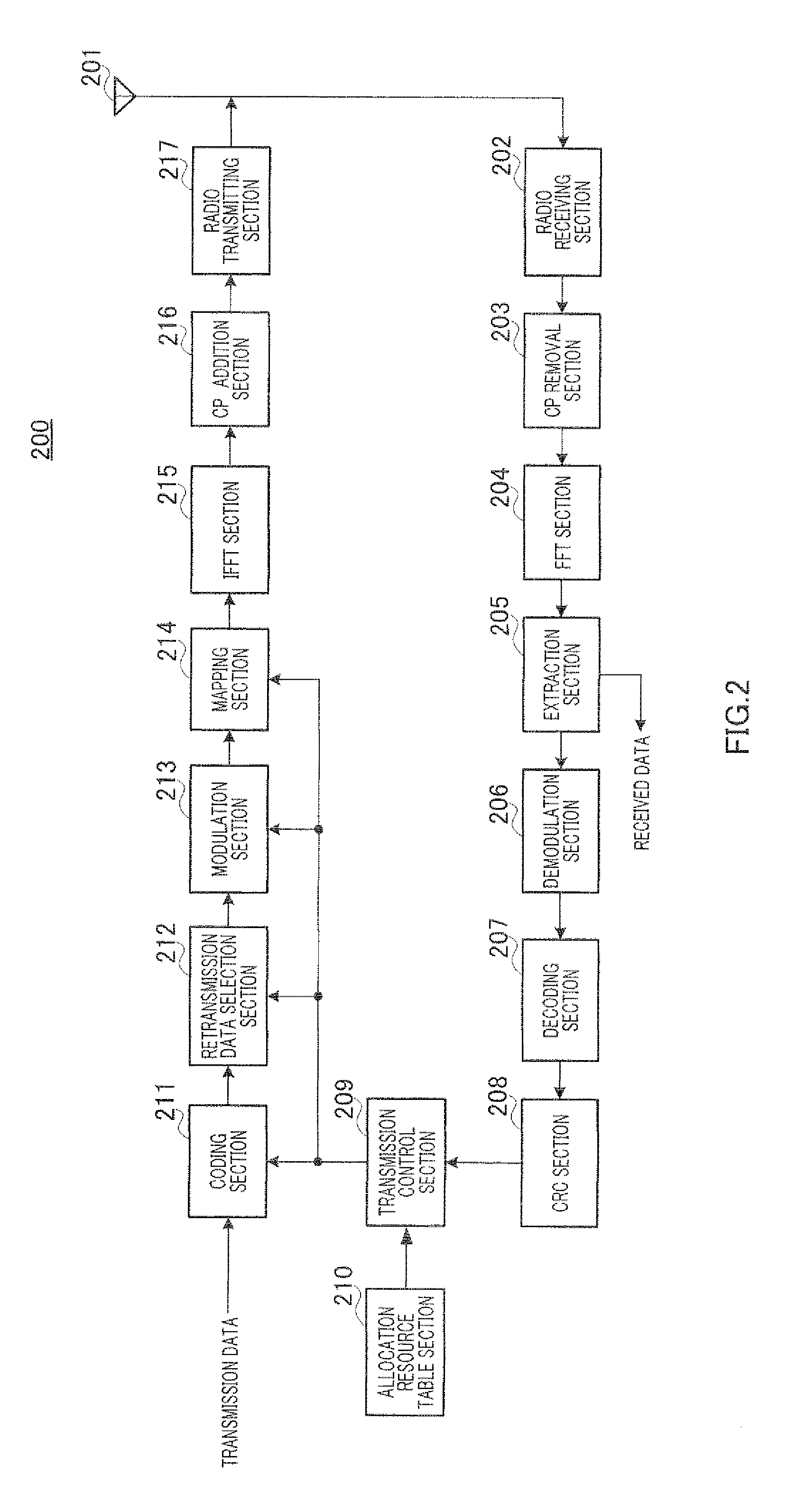
Provided is a radio transmission device which can simultaneously reduce: a radio resource consumption amount required for signaling to report band allocation information and a HARQ operation mode, and a transmission packet collision ratio accompanying a reception error of the band allocation information. The radio transmission device includes a transmission control unit (209) which inputs an encoding ratio, an initial transmission data range, a modulation method, a physical resource-to-be-transmitted position information to an encoding unit (211), a retransmission data selection unit (212), a modulation unit (213), and a mapping unit (214), respectively according the allocated radio resource and transmission parameter reported in the allocation information, if any allocation information is present. On the other hand, if no allocation information is present, the transmission control unit (209) judges whether to perform retransmission using a predetermined transmission parameter or terminate the retransmission according to the HARQ mode information and predetermined allocation radio resource information obtained from an allocation resource table unit (210).

Description

TECHNICAL FIELD[0001]The present invention relates to a radio transmission apparatus and a retransmission control method.BACKGROUND ART[0002]In mobile communication systems, ARQ (Automatic Repeat reQuest) is adopted to downlink data from a radio communication base station apparatus (hereinafter a “base station”) to a mobile communication mobile station apparatus (hereinafter a “mobile station”). That is, a mobile station (UE) feeds back a response signal showing a downlink data error detection result to a base station. A mobile station performs error detection for downlink data using CRC (Cyclic Redundancy Check), and feeds back an ACK (Acknowledgment) if CRC=OK (no error) or a NACK (Negative Acknowledgment) if CRC=NG (error present), as a response signal, to a base station. This response signal is transmitted to the base station using uplink control channels, including, for example, a PUCCH (Physical Uplink Control Channel) and an uplink L1 / L2 CCH (L1 / L2 Control Channel).[0003]Like...

Claims


Application Information

Patent Timeline
IPC IPC(8): H04L1/18
CPCH04L1/1812H04W72/0406H04L1/1887H04W72/20
Inventor IMAMURA, DAICHINISHIO, AKIHIKO
Owner PANASONIC CORP
Learn More