Cryogenic balloon device with radiofrequency tip

a radiofrequency tip and cryogenic balloon technology, applied in the field of cryogenic balloon device with radiofrequency tip, can solve the problems of increasing the risk of patient undergoing treatment, increasing the time required to perform the desired treatment, and limited in the ability to provide multiple ablative patterns to one or more tissue sites

Active Publication Date: 2015-12-08
MEDTRONIC CRYOCATH LP
View PDF12 Cites 27 Cited by
  • Summary
  • Abstract
  • Description
  • Claims
  • Application Information

AI Technical Summary

Benefits of technology

[0031]The disclosed system 10 provides a number of benefits and advantages. For example, providing multiple treatment regions with different treatment pattern capabilities allows a physician to tailor treatment to specific patients, as described above. It also allows a physician or user to create a first, larger pattern with the first treatment region 28, for example, and then follow up with the second treatment region 38 to create secondary, smaller patterns to fill in gaps or “touch up” the first treatment pattern. This may be particular convenient when attempting to isolate or otherwise ablate an anatomical structure such as a pulmonary vein (though other structures may be similarly treated) with a substantially continuous ablative pattern. The first treatment region 28 may be used to create substantially the entire desired pattern, with the second treatment region 38 used to treat missed or incongruous regions in the intended treatment region—resulting in a substantially continuous treatment pattern.

Problems solved by technology

Exchanging these various catheters during a procedure can cause inaccuracies or movement in the placement and location of the distal tip with respect to the tissue to be ablated, and may further add to the time required to perform the desired treatment.
These potential inaccuracies and extended duration of the particular procedure increase the risk to the patient undergoing treatment.
Accordingly, it would be desirable to provide a single medical device having the ability to provide ablative patterns of various shapes, without the need for additional catheters or the like having a single geometric orientation, and thus, limited in the ability to provide multiple ablative patterns to one or more tissue sites.

Method used


Image

  • Cryogenic balloon device with radiofrequency tip
  • Cryogenic balloon device with radiofrequency tip
  • Cryogenic balloon device with radiofrequency tip

Examples


Embodiment Construction

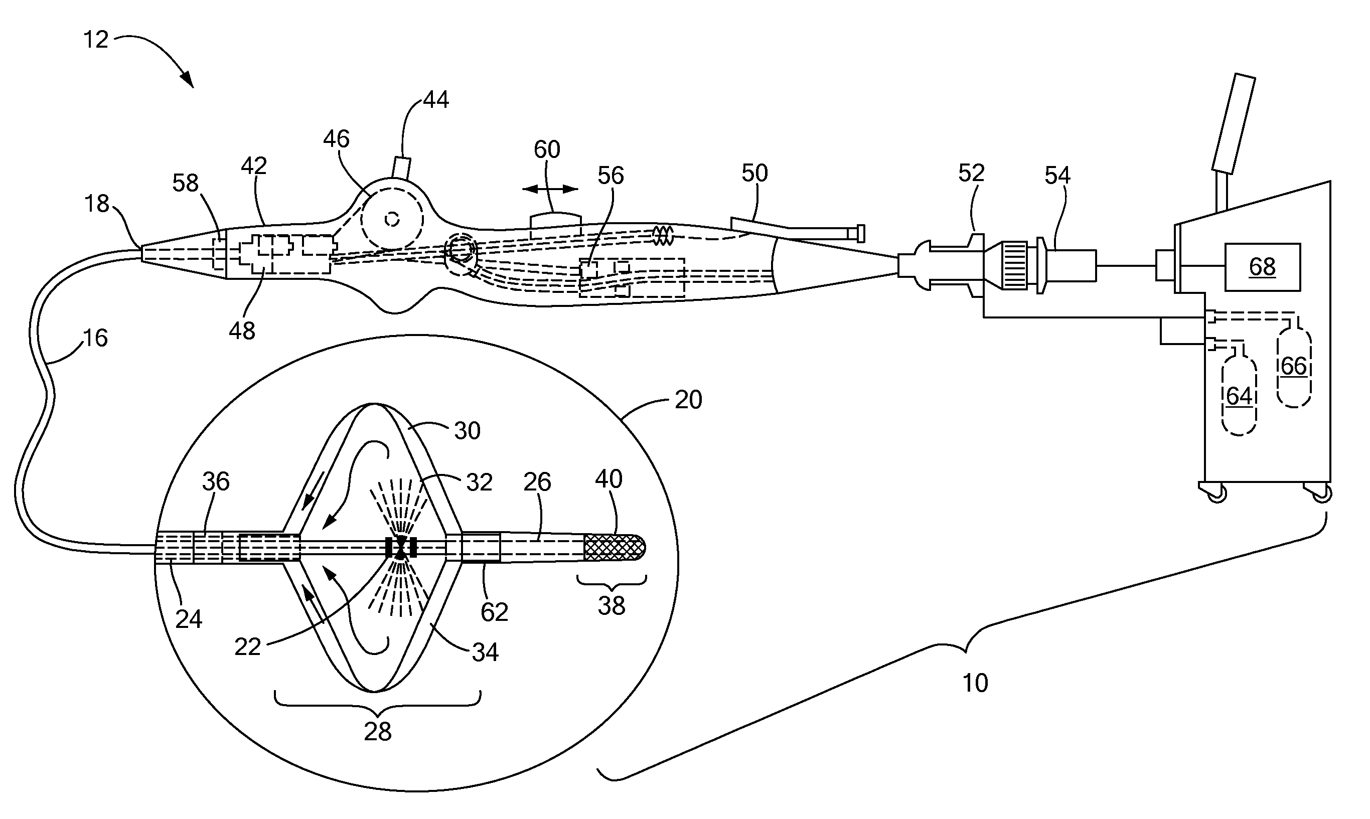
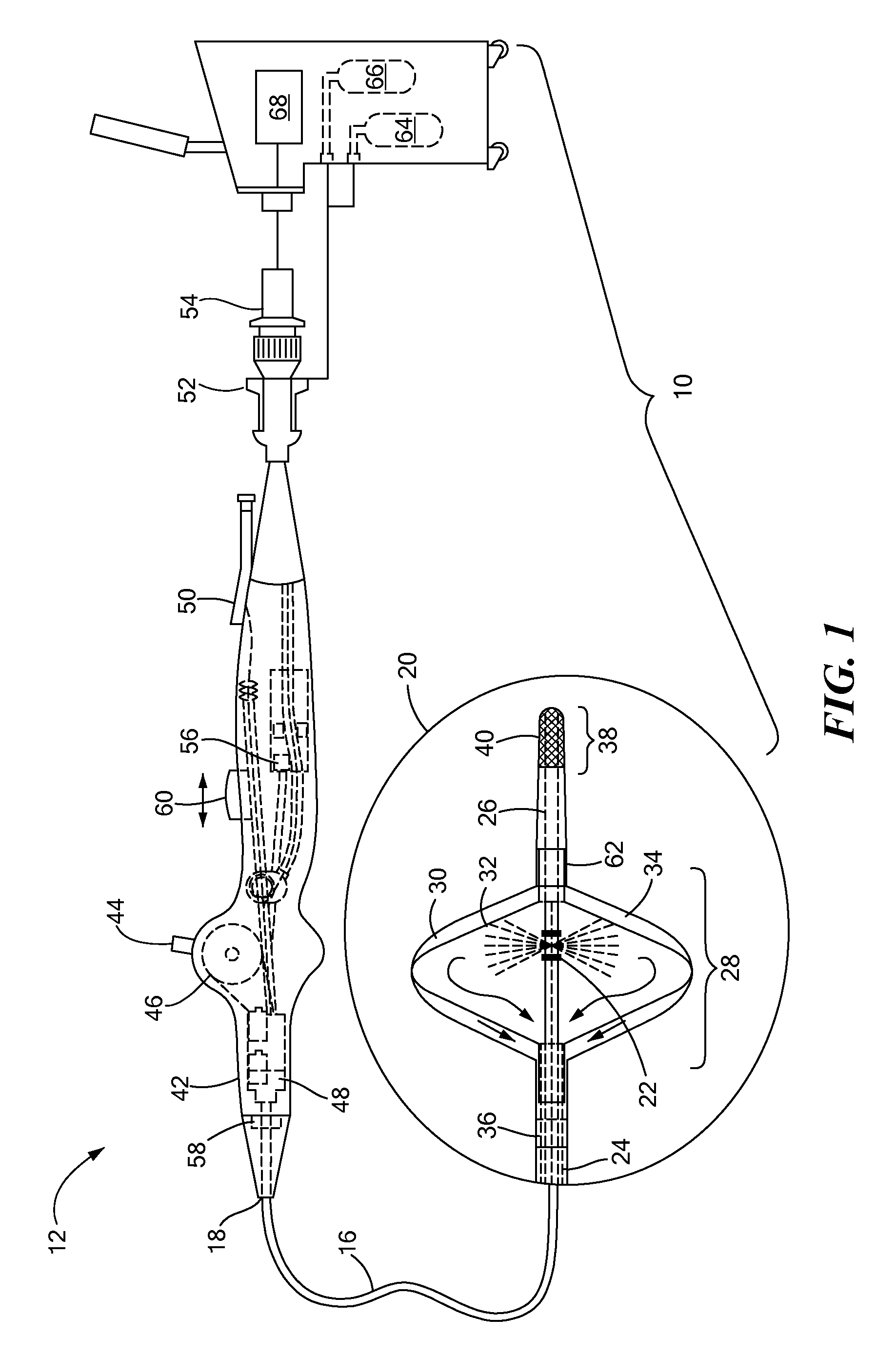
[0012]The present invention advantageously provides a medical system having the ability to provide ablative patterns of various shapes to treat one or more targeted tissue sites. Referring now to the drawing figures in which like reference designations refer to like elements, an example of a medical system constructed in accordance with principles of the present invention is shown in FIG. 1 and generally designated as “10.” The system 10 generally includes a medical device 12 that may be coupled to a control unit 14. The medical device 12 may include a medical probe, a catheter, or other instrument, and may generally include one or more treatment regions for energetic or other therapeutic interaction between the medical device 12 and a treatment site. The treatment region(s) may deliver, for example, cryogenic therapy, radiofrequency energy, electroporation energy or other energetic transfer with a tissue area in proximity to the treatment region(s), including cardiac tissue.

[0013]T...


PUM


Abstract

An intravascular ablation device, including a flexible elongate body; an expandable element positioned on the elongate body; a radiofrequency or electroporation treatment segment located distally of the expandable element; a cryogenic coolant source in fluid communication with an interior of the expandable element; and a radiofrequency or electroporation energy source in communication with the radiofrequency or electroporation treatment segment.

Description

CROSS-REFERENCE TO RELATED APPLICATION[0001]n / aSTATEMENT REGARDING FEDERALLY SPONSORED RESEARCH OR DEVELOPMENT[0002]n / aFIELD OF THE INVENTION[0003]The present invention relates to a method and system for thermal tissue treatment, and in particular, towards systems and methods of use thereof for treating one or more tissue sites having varying geometries with varying treatment modalities.BACKGROUND OF THE INVENTION[0004]Minimally invasive devices, such as catheters, are often employed for surgical procedure, including those involving ablation, dilation, and the like. In a particular situation, an ablation procedure may involve creating a series of inter-connecting lesions in order to electrically isolate tissue believed to be the source of an arrhythmia. During the course of such a procedure, a physician may employ several different catheters having variations in the geometry and / or dimensions of the ablative element in order to produce the desired ablation pattern. Each catheter may...

Claims


Application Information

Patent Timeline
Patent Type & Authority Patents(United States)
IPC IPC(8): A61B18/18A61B18/02A61B18/14A61B18/00
CPCA61B18/02A61B18/1492A61B2018/0022A61B2018/00255A61B2018/00357A61B2018/00613A61B2018/00642A61B2018/00702A61B2018/00714A61B2018/00791A61B2018/00863A61B2018/00898A61B2018/00994A61B2018/0212A61B2018/0262A61B2018/00375A61B2018/00351
Inventor LALONDE, JEAN-PIERRE
Owner MEDTRONIC CRYOCATH LP
Why Eureka
Try Eureka