Method for forming a protective coat about a cutback between pipes forming part of an underwater pipeline

Inactive Publication Date: 2010-07-29
SAIPEM SPA
View PDF12 Cites 15 Cited by
  • Summary
  • Abstract
  • Description
  • Claims
  • Application Information

AI Technical Summary

Benefits of technology

[0016]It is an object of the present invention to provide a method of forming a protective c

Problems solved by technology

All the above methods of applying the third coat are extremely time-consuming.
In other words, since, in most cases, the mass of polymer material to be applied to form the third coat is relatively considerable, and the third coat must be plastic enough, when applied, to achieve effective chemical/mechanical adhesion to the second coat, known methods of applying th

Method used


Image

  • Method for forming a protective coat about a cutback between pipes forming part of an underwater pipeline
  • Method for forming a protective coat about a cutback between pipes forming part of an underwater pipeline
  • Method for forming a protective coat about a cutback between pipes forming part of an underwater pipeline

Examples


Example

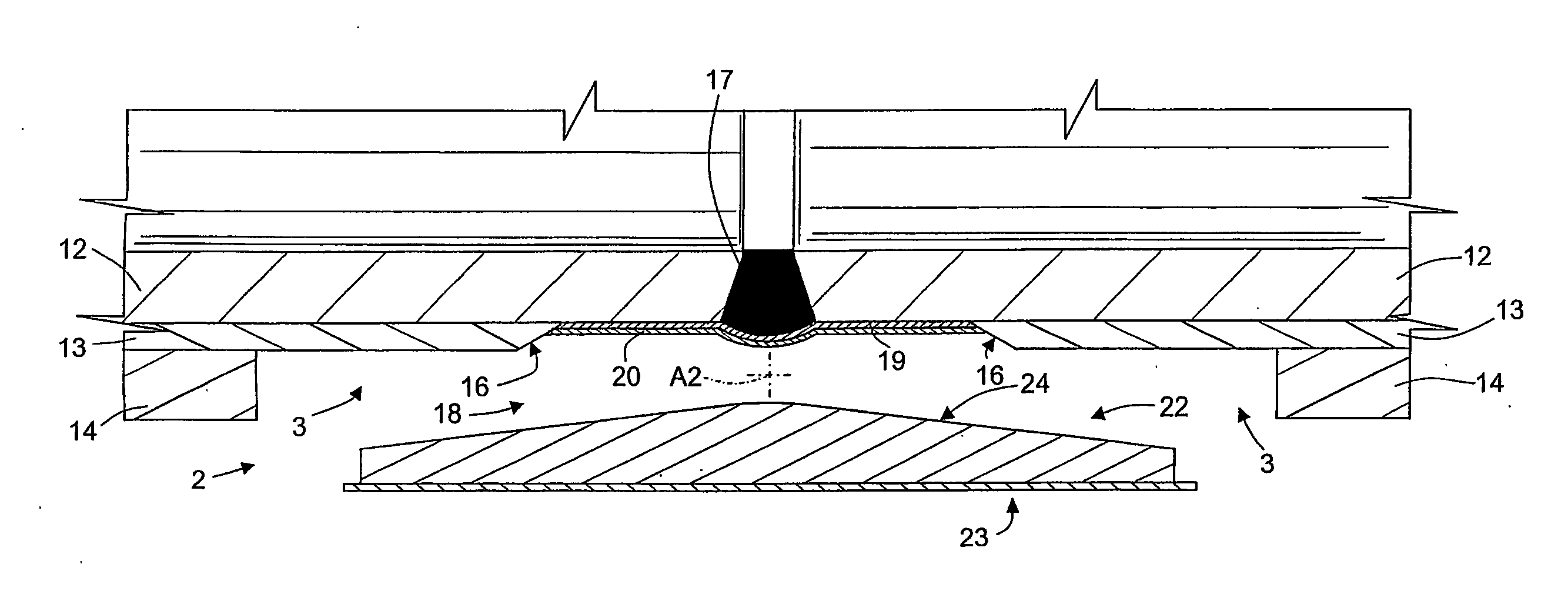
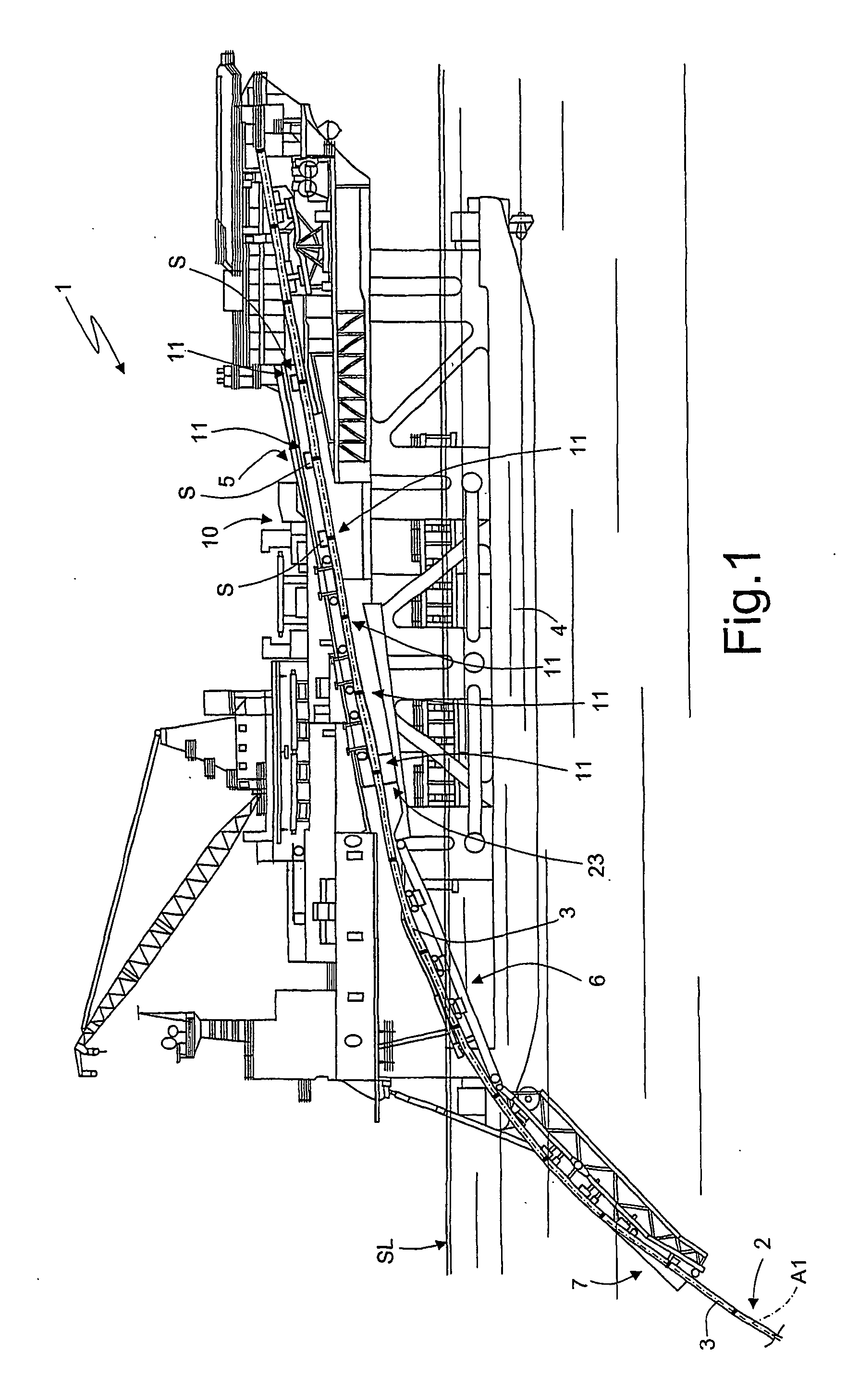
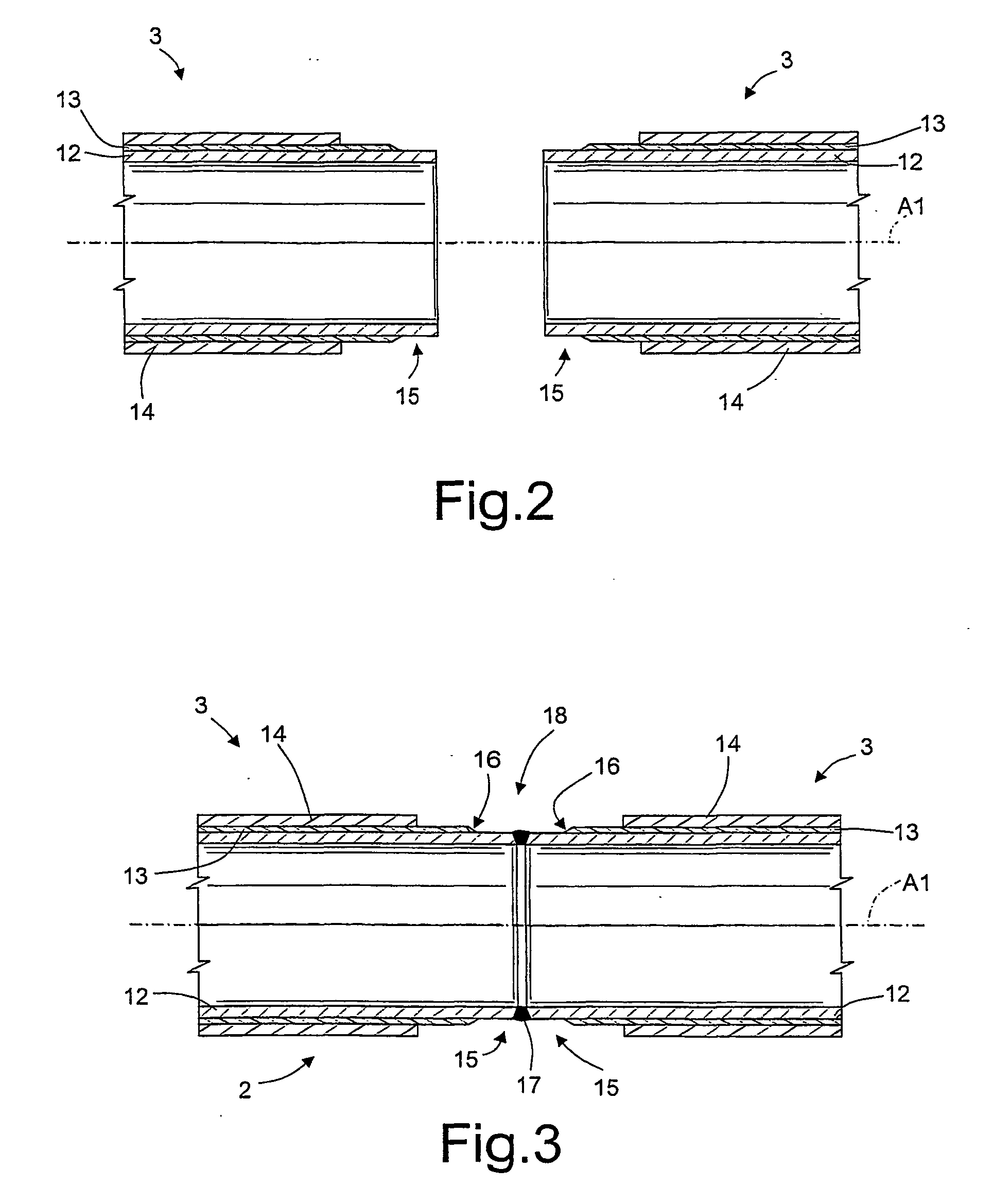
[0035]Number 1 in FIG. 1 indicates a pipeline-laying vessel in the process of producing and laying in the sea (SL indicates sea level) an underwater pipeline 2 comprising pipes 3 joined to one another. Vessel 1 comprises buoyancy hulls 4; an above-water tunnel 5; a partly above-water, inside ramp 6; an underwater outside ramp 7; and a work line 10 extending along tunnel 5 and the above-water portion of inside ramp 6.

[0036]The partly formed underwater pipeline 2 and pipes 3 ready for joining to it extend along an axis A1 of work line 10, which comprises a number of joining stations 11 equally spaced along axis A1, and each for performing a given operation, such as welding, non-destructive testing, or bridging a coating.

[0037]The distance between adjacent joining stations 11 equals the standard length, about 12 metres, of each pipe 3, or a multiple of the standard length, when joining, along line 10, multiple-standard-length pipes 3 joined beforehand at on-land installations or off-li...


PUM

PropertyMeasurementUnit
Temperatureaaaaaaaaaa
Lengthaaaaaaaaaa
Thicknessaaaaaaaaaa

Abstract

A method of forming a protective coat about a cutback between pipes forming part of an underwater pipeline provides for laying a thermoplastic sheet on a supporting sheet; and winding the thermoplastic sheet and the supporting sheet about the cutback to join the thermoplastic sheet to the cutback.

Description

TECHNICAL FIELD[0001]The present invention relates to a method of forming a protective coat about a cutback between pipes joined end to end to form underwater pipelines.[0002]The method according to the present invention forms part of general method of producing underwater pipelines, and which comprises, among other things, joining the facing free ends of two adjacent pipes, aligned along an axis, to form an annular joint portion known as a cutback; and winding a protective sheet about the cutback.BACKGROUND ART[0003]Underwater pipelines comprise a number of pipes joined to total lengths of hundreds of kilometers. The pipes are of normally 12-metre standard length, and relatively large diameters ranging between 0.2 and 1.5 metres, and each comprise a steel cylinder; a first coating of polymer material to protect the steel pipe; and possibly a second coating of Gunite or cement to weigh down the pipeline. In some applications, the pipes and underwater pipelines do not need and theref...

Claims


Application Information

Patent Timeline
IPC IPC(8): B29C63/06
CPCB29C63/06F16L13/0272F16L58/181B29C66/112B29C66/1122B29C66/12821B29C66/1286B29C66/5326B29C66/71B29C66/72321B29C66/7392B29C66/742B29C66/74283B29C65/028B29K2023/06B29K2023/12
Inventor BERGONZIO, VALERIO
Owner SAIPEM SPA
Why Eureka
Try Eureka