Systems and methods for fabricating a dental template

a template and dental technology, applied in the field of orthodontics, can solve the problems of prolonging the procedure, treatment providers may have difficulty in seeing the precise position of the bracket relative, and the optimal surface for bracket placement is difficult to access, so as to improve treatment precision and minimize the variation in distance and angle perception

Inactive Publication Date: 2015-12-08
ALIGN TECH
View PDF218 Cites 40 Cited by
  • Summary
  • Abstract
  • Description
  • Claims
  • Application Information

AI Technical Summary

Benefits of technology

[0008]Advantages of the template may include one or more of the following. The template can be used for etching or for positioning brackets on teeth. The treatment can be done virtually and the placement of the brackets can be done using a template device that is a removable guide. This device allows precise placement of the bracket and enables bracket placement onto specific teeth independent of overall arch geometry. The template makes it easier for a less well-trained or an untrained person to bond a bracket. The system minimizes variations in the perception of distance and angles. The template provides a very precise control on the placement of the bracket. Since bracket placement is one of the critical variables to successful treatment, the template improves treatment precision from patient to patient and from tooth to tooth.

Problems solved by technology

One shortcoming with this technique is the difficulty in accessing the optimal surface for bracket placement on severely crowded teeth or in teeth where the bonding surface is obstructed by teeth in the opposing arch during jaw closure.
With posterior teeth, the treatment provider may have difficulty seeing the precise position of the bracket relative to the tooth surface.
Also, the necessity of minimizing moisture contamination from the patient's saliva can prolong the procedure and also unduly impair the accuracy of placement of the brackets on the teeth.
All of these factors increase the chance that the ultimate adhesive bond will not have sufficient strength to retain the brackets on the teeth during treatment.
This method however, is labor intensive.
An additional problem with the indirect method is that brackets may become dislodged during the removal of the matrix from the dental arches.
The problem of proper access to tooth surfaces for optimal placement in the event of severely crooked teeth or teeth which interfere with the opposing arch such that brackets cannot be placed is also not addressed.

Method used


Image

  • Systems and methods for fabricating a dental template
  • Systems and methods for fabricating a dental template
  • Systems and methods for fabricating a dental template

Examples


Embodiment Construction

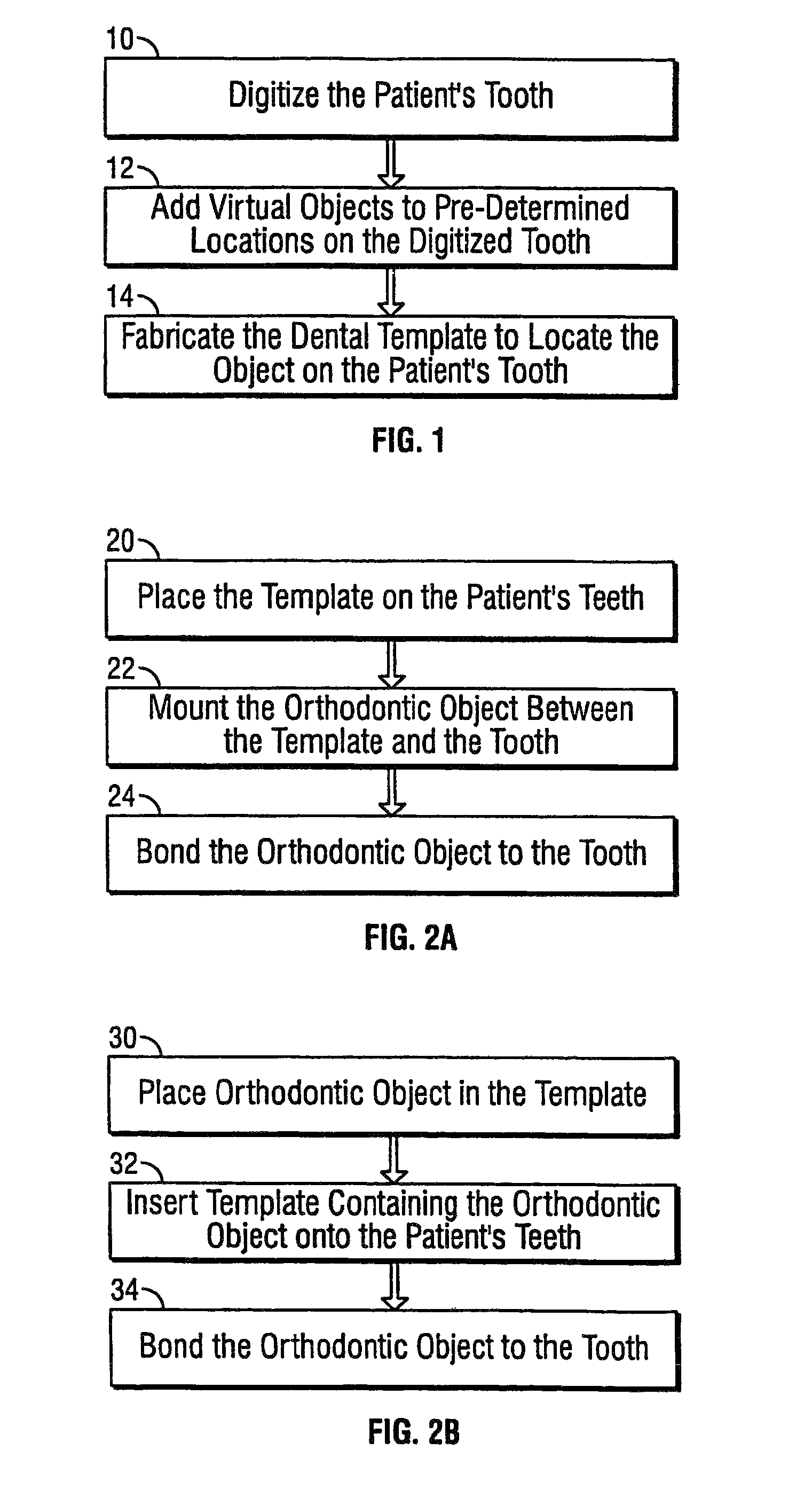
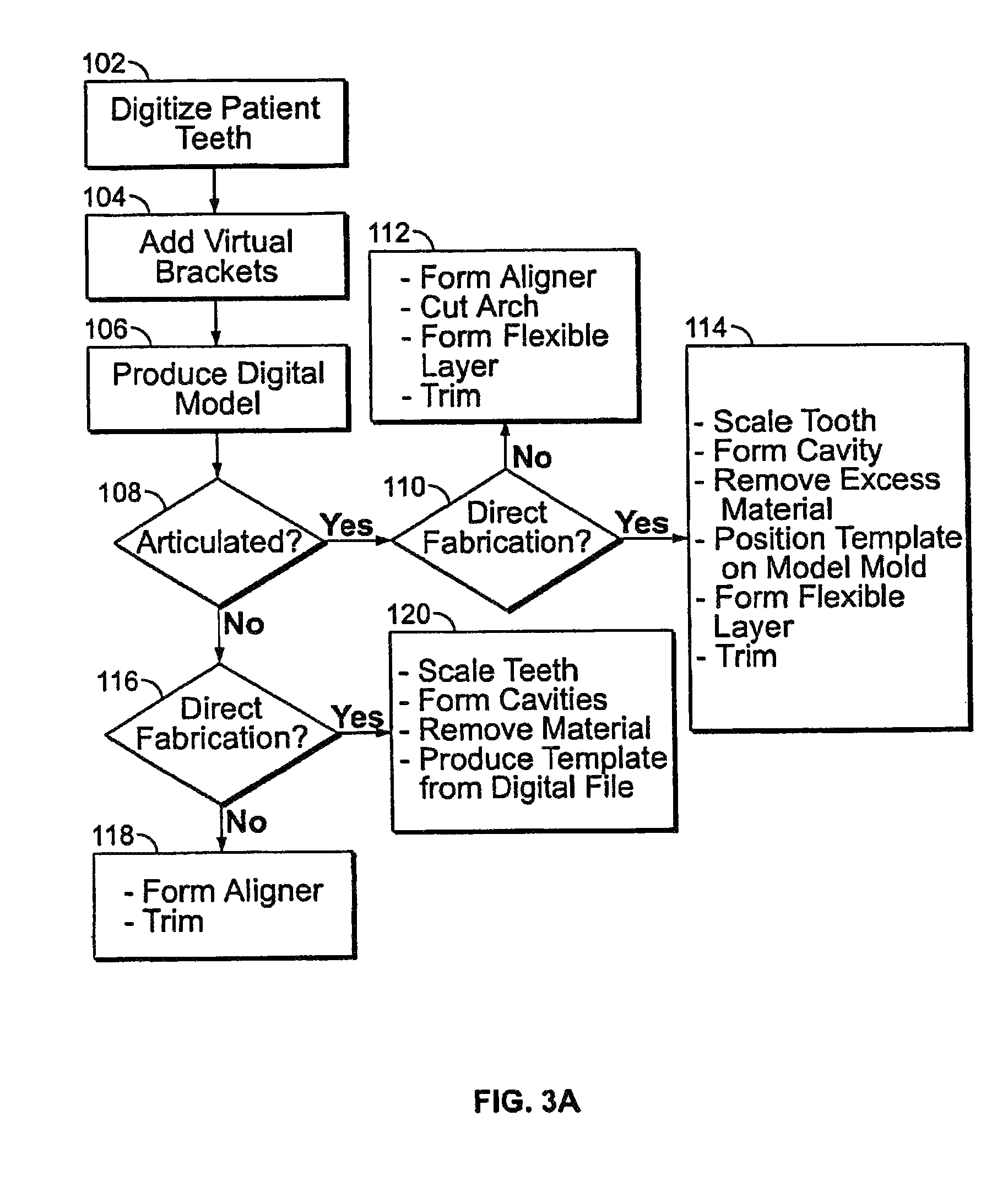
[0019]FIG. 1 shows an exemplary method or process to fabricate a dental template to position an object on a patient's tooth. First, the process digitizes the patient's tooth (10). Next, virtual objects are added to pre-determined locations on the digitized tooth (12). Finally, the process fabricates the dental template to locate the object on the patient's tooth (14). One detailed implementation of FIG. 1 is described in FIGS. 3A and 3B below.

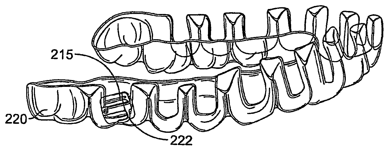
[0020]FIG. 2A shows an exemplary method or process for placing an orthodontic object on a patient's tooth. The process uses the template fabricated in the process of FIG. 1. The process includes placing the template on the patient's teeth (20); mounting the orthodontic object between the template and the tooth (22); and bonding the orthodontic object to the tooth (24). In the bonding operation, chemical curing or light curing adhesives can be used. In chemical curing, separately supplied curing components are mixed together and a small quantity...


PUM

PropertyMeasurementUnit
thicknessaaaaaaaaaa
flexibleaaaaaaaaaa
forcesaaaaaaaaaa

Abstract

A dental template to position an object on a patient's tooth includes digitizing the patient's tooth; adding virtual objects to predetermined locations on the digitized tooth; and fabricating the dental template to locate the object on the patient's tooth. The template can be used for etching or for positioning brackets on teeth.

Description

CROSS-REFERENCE[0001]The present application is a Continuation of U.S. application Ser. No. 13 / 620,209, filed on Sep. 14, 2012, which is a Continuation of U.S. application Ser. No. 11 / 297,129, filed on Dec. 7, 2005, now U.S. Pat. No. 8,496,473, which is a Continuation of U.S. application Ser. No. 10 / 870,808, filed on Jun. 17, 2004, now U.S. Pat. No. 7,056,115, which is a Continuation of U.S. application Ser. No. 10 / 375,223, filed on Feb. 26, 2003, the full disclosures of which are incorporated herein by reference.BACKGROUND OF THE INVENTION[0002]The present invention relates generally to the field of orthodontics.[0003]One objective in orthodontics is to move a patient's teeth to a position where the teeth function optimally and are also aesthetically pleasing. Conventional appliances such as braces and wires can be positioned on a patient's teeth by a treatment provider such as an orthodontist or a suitably trained dentist. Once mounted on the teeth, the hardware exerts continual f...

Claims


Application Information

Patent Timeline
Patent Type & Authority Patents(United States)
IPC IPC(8): A61C3/00A61C7/00A61C7/14A61C13/00
CPCA61C7/002A61C7/146A61C13/0004Y10T29/49568B29C64/135B33Y80/00B33Y50/02B29L2031/753
Inventor PHAN, LOC X.KNOPP, PETER G.KUO, ERIC E.ABOLFATHI, AMIRWEN, HUAFENG
Owner ALIGN TECH
Why Eureka
Try Eureka