Image forming apparatus with registration rollers configured to reset the lateral position of a sheet

a technology of image forming apparatus and registration roller, which is applied in the direction of electrographic process apparatus, thin material processing, instruments, etc., can solve the problems of inability to match, displacement correction may not be appropriately performed, and the variation of translation responsiveness with time is not taken into account, so as to achieve accurate displacement correction, limit the increase of cpp, and the effect of precise alignmen

Active Publication Date: 2015-12-08
KONICA MINOLTA INC
View PDF6 Cites 2 Cited by
  • Summary
  • Abstract
  • Description
  • Claims
  • Application Information

AI Technical Summary

Benefits of technology

[0017]An object of the present invention is to provide an image forming apparatus capable of limiting increase in CPP, as well as achieving an appropriate displacement correction even when the components of the apparatus is degraded because of the operating condition, and a precise alignment of an image with a sheet.

Problems solved by technology

The cause of this displacement includes, for example, an axially nonuniform roller diameter due to errors in manufacture, a variation in roller diameter due to aging degradation, a displaced sheet stored in the sheet feed tray, and the like.
However, in practice, the translation amount of registration rollers R based on a translation command value and the actual translation amount (measured value) of a sheet do not match.
However, the translation control table is set at the manufacturing stage of the image forming apparatus, and the variation of the translation responsiveness with time is not taken into consideration.
That is, when the translation responsiveness is varied due to the operating condition (such as the number of printed sheets) of the image forming apparatus and the like, sheets may not be translated by the required translation amount even when the registration rollers are translated in accordance with the initially set translation control table, and thus the displacement correction may not be appropriately performed.
However, depending on the use environment, the components of the registration translation mechanism are replaced even when they are still usable, thus resulting in increase in cost per print (CPP).

Method used


Image

  • Image forming apparatus with registration rollers configured to reset the lateral position of a sheet
  • Image forming apparatus with registration rollers configured to reset the lateral position of a sheet
  • Image forming apparatus with registration rollers configured to reset the lateral position of a sheet

Examples


Embodiment Construction

[0033]In the following, an embodiment of the present invention will be described in detail with reference to the accompanying drawings.

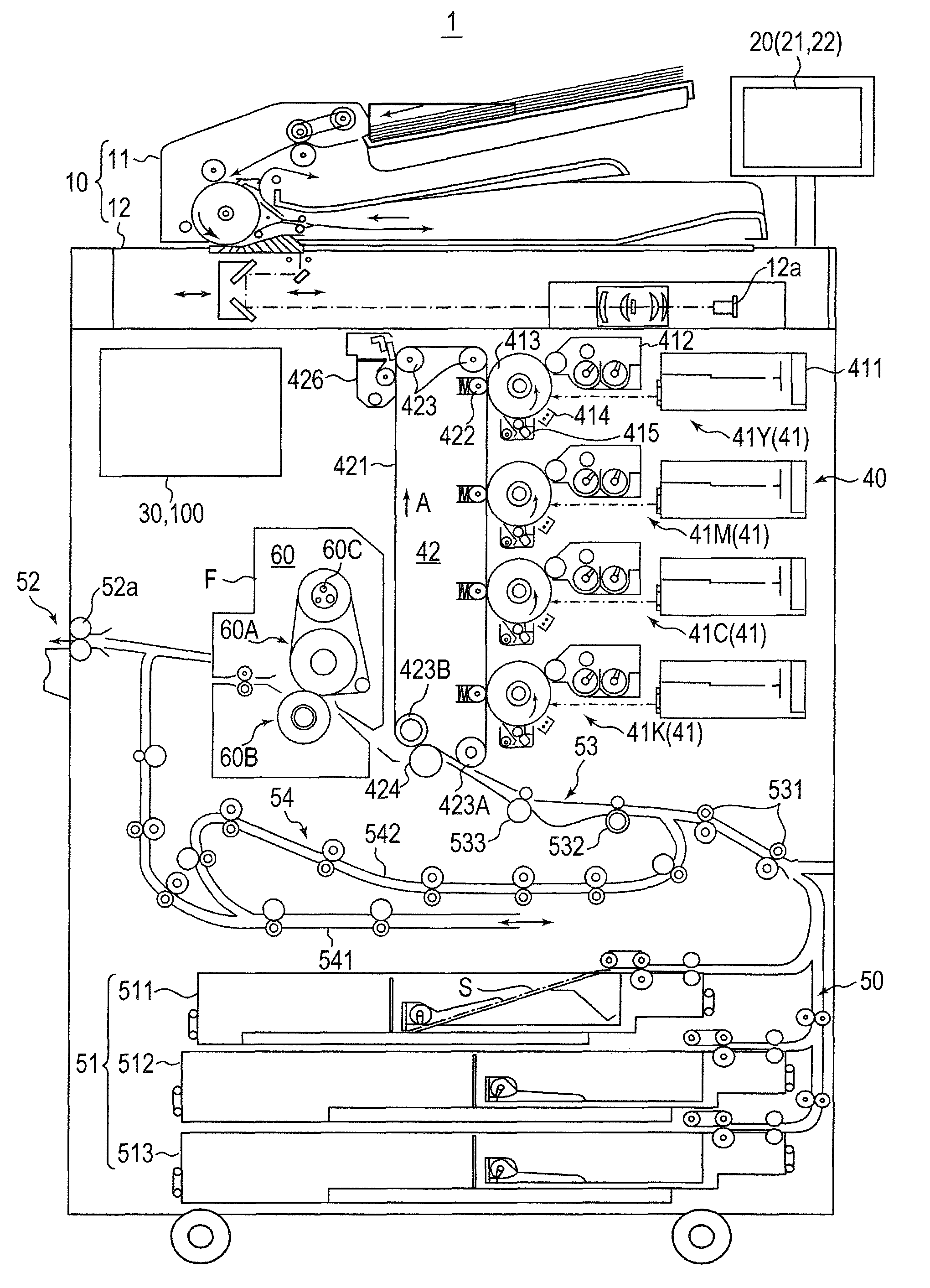
[0034]FIG. 4 illustrates an overall configuration of image forming apparatus 1 according to the embodiment of the present invention. FIG. 5 illustrates a principal part of a control system of image forming apparatus 1 according to the embodiment.

[0035]Image forming apparatus 1 illustrated in FIGS. 4 and 5 is a color image forming apparatus with an intermediate transfer system using electrophotographic process technology. A longitudinal tandem system is adopted for image forming apparatus 1. In the longitudinal tandem system, respective photoconductor drums 413 corresponding to the four colors of YMCK are placed in series in the travelling direction (vertical direction) of intermediate transfer belt 421, and the toner images of the four colors are sequentially transferred to intermediate transfer belt 421 in one cycle.

[0036]That is, image forming appa...


PUM


Abstract

An image forming apparatus includes: an image forming section; a pair of registration rollers; a displacement detection section; a displacement correction section; a translation amount determination section; and a control section configured to refer to a translation control table, operate the displacement correction section in accordance with a translation command value corresponding to a detection result obtained by the displacement detection section, obtain at a predetermined timing a relationship between the translation command value and a translation amount of the sheet, and update the translation control table on the basis of the relationship. The control section updates the translation control table when a displacement of a sheet is correctable, but does not update the translation control table when a displacement of a sheet is correctable.

Description

CROSS REFERENCE TO RELATED APPLICATIONS[0001]This application is entitled to and claims the benefit of Japanese Patent Application No. 2013-148292, filed on Jul. 17, 2013, the disclosure of which including the specification, drawings and abstract is incorporated herein by reference in its entirety.BACKGROUND OF THE INVENTION[0002]1. Field of the Invention[0003]The present invention relates to an electrophotographic image forming apparatus.[0004]2. Description of Related Art[0005]In general, an electrophotographic image forming apparatus (such as a printer, a copy machine, and a fax machine) is configured to irradiate (expose) a charged photoconductor (for example, a photoconductor drum) with (to) laser light based on image data to form an electrostatic latent image on the surface of the photoconductor. The electrostatic latent image is then visualized by supplying toner from a developing device to the photoconductor on which the electrostatic latent image is formed, whereby a toner ...

Claims


Application Information

Patent Timeline
Patent Type & Authority Patents(United States)
IPC IPC(8): G03G15/00B65H9/00
CPCG03G15/6561B65H9/002G03G15/55G03G15/6567G03G2215/00561G03G15/6558
Inventor KAWABATA, SHINICHIKAWANAGO, YUSUKEOKUBO, TAKAHIRO
Owner KONICA MINOLTA INC
Why Eureka
Try Eureka