Connector and conduction path

a technology of conduction path and connection tube, which is applied in the direction of connection contact material, electrical apparatus casing/cabinet/drawer, connection device connection, etc., can solve the problems of increasing so as to limit the increase in the pressure inside the protective tube.

Active Publication Date: 2021-10-19
SUMITOMO WIRING SYST LTD
View PDF29 Cites 1 Cited by
  • Summary
  • Abstract
  • Description
  • Claims
  • Application Information

AI Technical Summary

Benefits of technology

[0006]With this structure, when the wire-side connector and the device-side connector are finally fitted to each other, the ventilation passage, which connects the inner space of the device and the inner space of the protective tube through the first through hole of the wire-side connector and the second through hole of the device-side connector, is formed inside the wire side connector and the device-side connector. Thus, even when the temperature increases inside the protective tube, the air inside the protective tube is released into the inner space of the device to limit increases in the pressure inside the protective tube. Further, the ventilation passage is formed inside the wire-side connector and the device-side connector. This avoids situations in which the ventilation passage is clogged by flying objects when the vehicle is traveling or dust that is suspended in the air. Accordingly, increases in the pressure inside the protective tube can be limited.

Problems solved by technology

The arrangement of the ventilation portion in the water resistant cover may result in flying objects, which are lifted when the vehicle is traveling, to clog the ventilation portion thereby increasing the pressure inside the protective tube.
Accordingly, increases in the pressure inside the protective tube can be limited.

Method used


Image

  • Connector and conduction path
  • Connector and conduction path
  • Connector and conduction path

Examples


first embodiment

[0018]A first embodiment will now be described with reference to FIGS. 1 to 7.

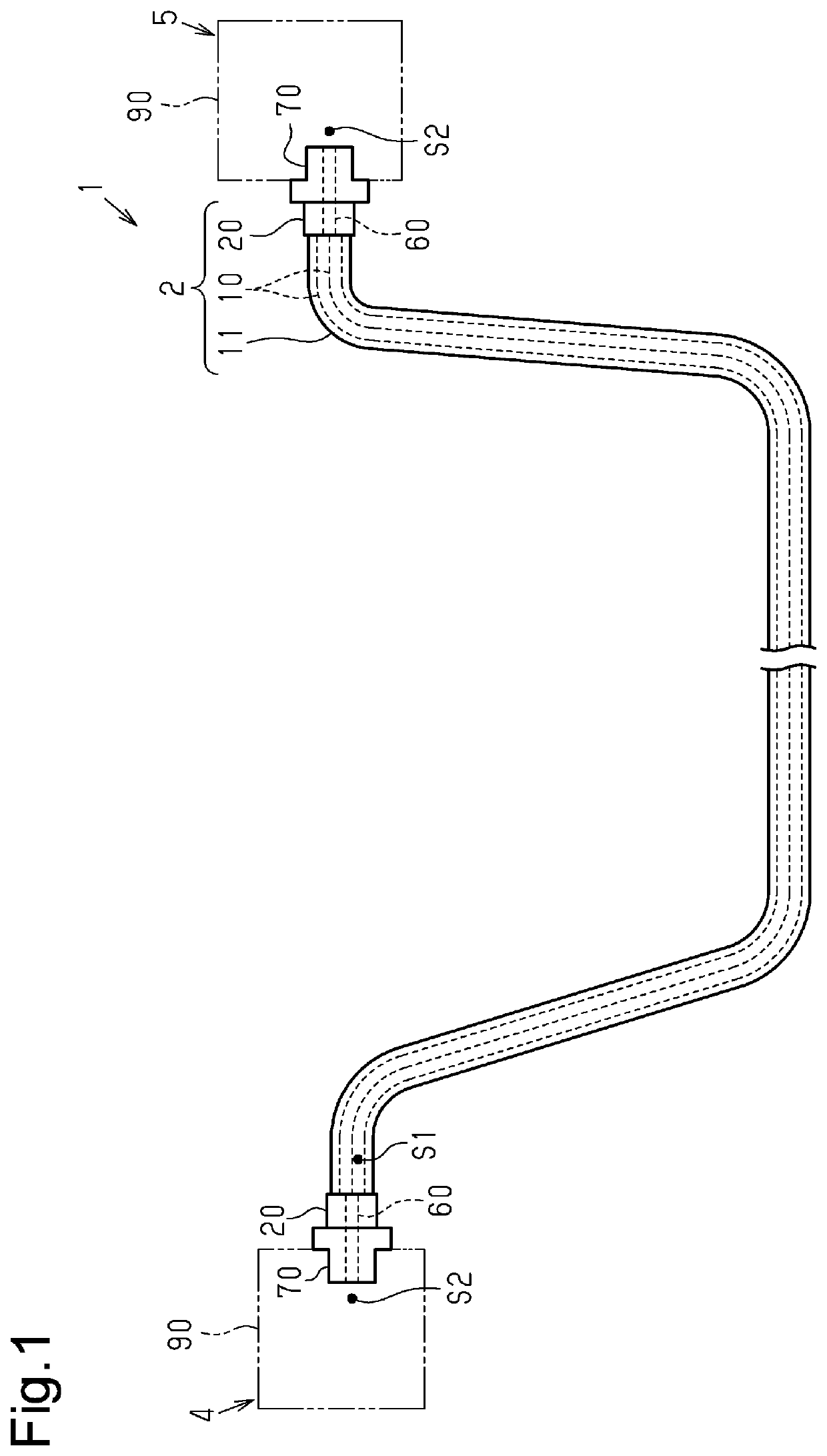
[0019]FIG. 1 shows a conduction path 1 connecting two, three, or more electric devices (devices). The conduction path 1 includes a wire harness 2 and two device-side connectors 70 connected to the two ends of the wire harness 2. The conduction path 1 includes an inverter 4, which is arranged at, for example, a front part of a vehicle such as a hybrid vehicle or an electric vehicle, and a high-voltage battery 5, which is arranged toward the rear of the vehicle from the inverter 4. The conduction path 1 is laid out, for example, under the floor of the vehicle. The inverter 4 is connected to a wheel driving motor (not shown) that serves as a power source when the vehicle travels. The inverter 4 generates AC power from the DC power of the high-voltage battery 5 and supplies the AC power to the motor. The high-voltage battery 5 is, for example, a battery capable of supplying several hundred bolts of voltage.

[00...

second embodiment

[0075]In the second embodiment, the ventilation film 50 is arranged on the rear end surface 26A of the tubular portion 26. However, as long as the entrance of water into the case 90 of a device can be restricted, the location of the ventilation film 50 is not particularly limited. For example, the ventilation film 50 can be arranged on the device-side connector housing 71 to close the front open end 78A of the through hole 78.

[0076]The ventilation film 50 of the second embodiment is a single layer. However, this is not a limitation. A further porous body, foam, woven fabric, non-woven fabric, net, mesh, or the like may be laminated as a reinforcement layer on the ventilation film 50.

[0077]In each of the above embodiments, the wire-side connector 20 includes the shield shell 24. However, this is not a limitation. The shield shell 24 can be provided when necessary, and the shield shell 24 can be omitted.

[0078]In each of the above embodiments, devices such as the inverter 4 and the hig...


PUM


Abstract

This connector is provided with: an apparatus-side connector (70) attached to an apparatus having a case (90); and a wire-side connector (20) to which a protective pipe (11) that protects a wire (10) is attached. A through hole (27) is formed inside the wire-side connector (20). A through hole (78) is formed inside the apparatus-side connector (70). When the wire-side connector (20) and the apparatus-side connector (70) are normally fitted, an air passage (60) communicating the inner space (S2) of the case (90) of the apparatus and the inner space (S1) of the protective pipe (11) through the through hole (27) and the through hole (78) is formed inside the wire-side connector (20) and the apparatus-side connector (70).

Description

BACKGROUNDField of the Disclosure[0001]The present disclosure relates to a connector and a conduction path.Related Art[0002]Conventionally, wires are covered by a protective tube for protection from water, dust, and the like. Wires are laid out in various forms. Thus, a protective tube is configured as a coupled body of various types of tubes having different structures. For example, a protective tube includes a pipe that protects an intermediate portion of the wires and a rubber water resistant cover that protects a portion between the pipe and a connector. The protective tube seals the portions between a connector at one end of the wires and a connector at the other end of the wires. The pressure inside a protective tube may increase due to a temperature change in the protective tube, a change in the atmospheric pressure, or the like. To limit such an increase in the pressure inside the protective tube, the water resistant cover includes a ventilation portion (refer to, for exampl...

Claims


Application Information

Patent Timeline
Patent Type & Authority Patents(United States)
IPC IPC(8): H01R4/64H01R13/52H05K7/20
CPCH01R13/5208H01R13/5202H05K7/20127H01R2201/26H01R13/6596H01R13/5219H05K5/0247H02G3/0462
Inventor ARAKI, YUSUKE
Owner SUMITOMO WIRING SYST LTD
Why Eureka
Try Eureka