Supercharge Your Innovation With Domain-Expert AI Agents!

Network interface with low power data transfer and methods for use therewith

a network interface and low power technology, applied in the field of network interfaces, can solve the problems of idle signals on the link, energy waste, and energy consumption of idle signals

Inactive Publication Date: 2015-12-08
AVAGO TECH INT SALES PTE LTD
View PDF4 Cites 2 Cited by
  • Summary
  • Abstract
  • Description
  • Claims
  • Application Information

AI Technical Summary

Problems solved by technology

Energy costs continue to escalate in a trend that has accelerated in recent years.
Such being the case, various industries have become increasingly sensitive to the impact of those rising costs.
The transmission of idle signals on a link wastes energy and adds to the radiated emission levels.
The disadvantages of conventional approaches will be evident to one skilled in the art when presented the disclosure that follows.

Method used


Image

  • Network interface with low power data transfer and methods for use therewith
  • Network interface with low power data transfer and methods for use therewith
  • Network interface with low power data transfer and methods for use therewith

Examples


Embodiment Construction

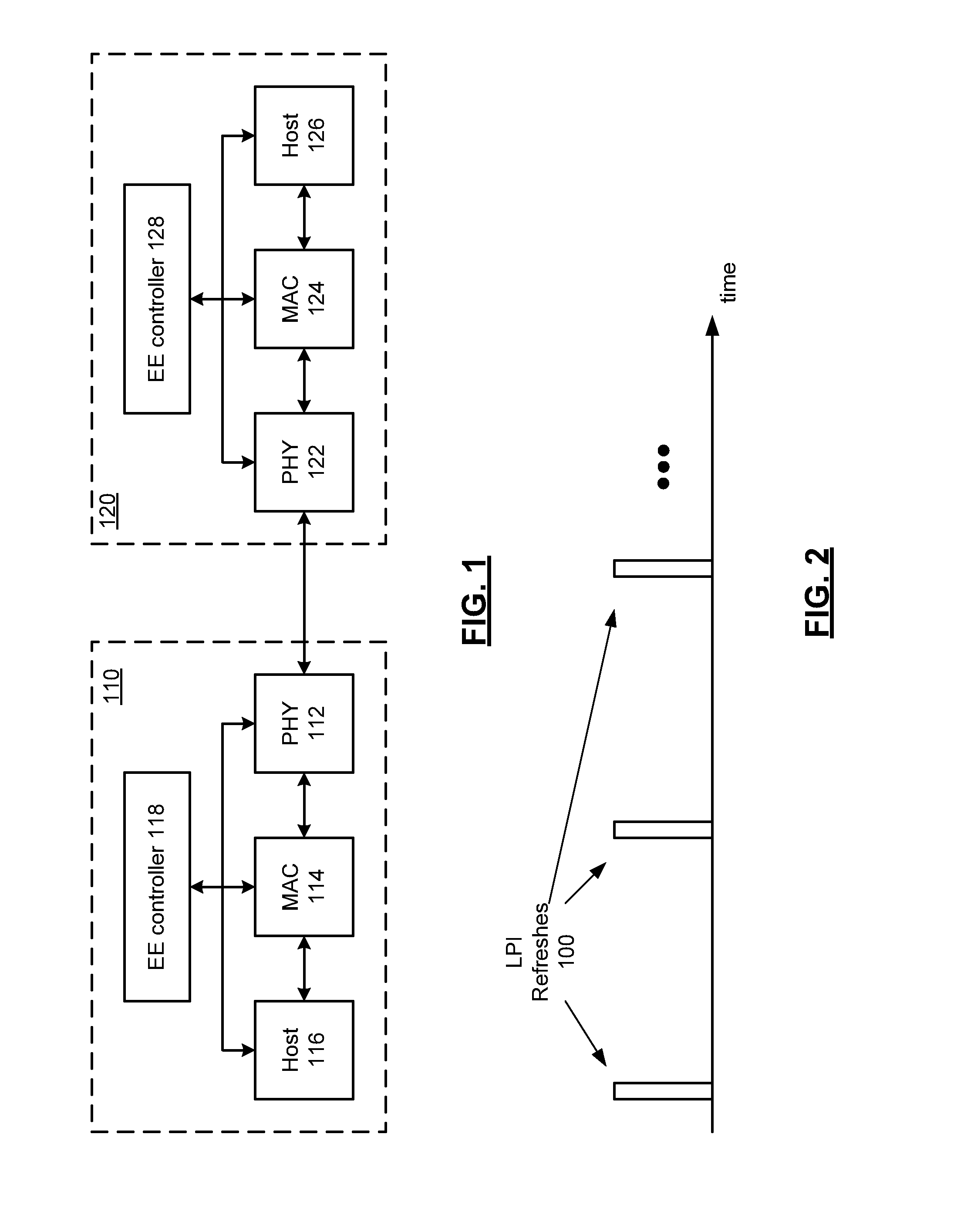
[0017]FIG. 1 is a schematic block diagram of an embodiment of two devices connected via a network link in accordance with the present invention. In particular, a network link is shown to which an energy efficiency control policy can be applied. As illustrated, the link supports communication between a first link partner 110 and a second link partner 120. In various embodiments, link partners 110 and 120 can each represent a network device such as a switch, router, endpoint (e.g., server, client device, VoIP phone, wireless access point, router, etc.), or other network device. As illustrated, link partner 110 includes physical layer device (PHY) 112, media access control module (MAC) 114, and host 116, while link partner 120 includes PHY 122, MAC 124, and host 126.

[0018]In general, hosts 116 and 126 may comprise a processing unit or other suitable logic, circuitry, and / or code that may enable operability and / or functionality of the five highest functional layers for data packets that...


PUM


Abstract

A network interface includes a physical layer device coupled to a network link. A media access control module communicates with a link partner over the network link. An energy controller monitors a link utilization level of the network link and transitions, in response to the monitoring, the media access control module and the physical layer device to a low power idle mode, wherein the low power idle mode includes periodic transmission of a plurality of refresh frames in a refresh cycle and wherein at least one of the plurality of refresh frames is modified to include at least one first data payload.

Description

CROSS REFERENCE TO RELATED PATENTS[0001]The present U.S. Utility Patent Application claims priority pursuant to 35 U.S.C. §119(e) to the following U.S. Provisional Patent Application which is hereby incorporated herein by reference in its entirety and made part of the present U.S. Utility Patent Application for all purposes:[0002]1. U.S. Provisional Application No. 61 / 763,783, entitled, NETWORK INTERFACE WITH LOW POWER DATA TRANSFER AND METHODS FOR USE THEREWITH, filed on Feb. 12, 2013.STATEMENT REGARDING FEDERALLY SPONSORED RESEARCH OR DEVELOPMENTINCORPORATION-BY-REFERENCE OF MATERIAL SUBMITTED ON A COMPACT DISC[0003]NOT APPLICABLEBACKGROUND OF THE INVENTION[0004]1. Technical Field of the Invention[0005]This invention relates generally to network interfaces such as an Ethernet interface devices.[0006]2. Description of Related Art[0007]Energy costs continue to escalate in a trend that has accelerated in recent years. Such being the case, various industries have become increasingly s...

Claims


Application Information

Patent Timeline
Patent Type & Authority Patents(United States)
IPC IPC(8): G06F1/32
CPCG06F1/3209G06F1/3278Y02B60/44Y02D10/00Y02D30/00Y02D30/50
Inventor MANAVGRABA, JAMES
Owner AVAGO TECH INT SALES PTE LTD
Features
  • R&D
  • Intellectual Property
  • Life Sciences
  • Materials
  • Tech Scout
  • Unparalleled Data Quality
  • Higher Quality Content
  • 60% Fewer Hallucinations
Learn More