Radiotherapy treatment device comprising image acquisition device and irradiation device, and radiotherapy method

a radiation therapy and treatment device technology, applied in radiation therapy, x-ray/gamma-ray/particle irradiation therapy, radiation therapy, etc., can solve the problems of severe limitations in three-dimensional imaging capability, severe side effects, and substantial irradiation of the entire organ

Active Publication Date: 2015-12-15
SIEMENS HEALTHCARE GMBH
View PDF16 Cites 17 Cited by
  • Summary
  • Abstract
  • Description
  • Claims
  • Application Information

AI Technical Summary

Benefits of technology

[0011]The treatment device therefore enables a complicated and expensive integration of irradiation device and imaging device to be avoided in order instead to allow a “shuttle mode of operation” of existing subsystems in relation to a permanently stationary patient positioning device. In this way the implementation overhead is reduced to the mounting or guidance of the subsystems, though solutions for this purpose, for example from the field of intraoperative magnetic resonance or computed tomography, are already well-known. A particular advantage of the invention in this regard is that there is nonetheless no requirement to move the patient during the radiation therapy. As is generally known, a patient is not a rigid system and can react to movements with changes, so that movements of the patient, in particular rotary movements, can be largely or preferably completely avoided by means of the present treatment device. The radiotherapy device and the image acquisition device are moved instead. The fact that a movement of the patient is not really necessary is also of psychological advantage to the patient, who can have greater confidence that the irradiation target will be reached correctly.
[0012]Actual possibilities for realizing a movement of subsystems which continue to be functionally largely independent are to be expounded in more detail hereinbelow and are described by means of the dependent claims.
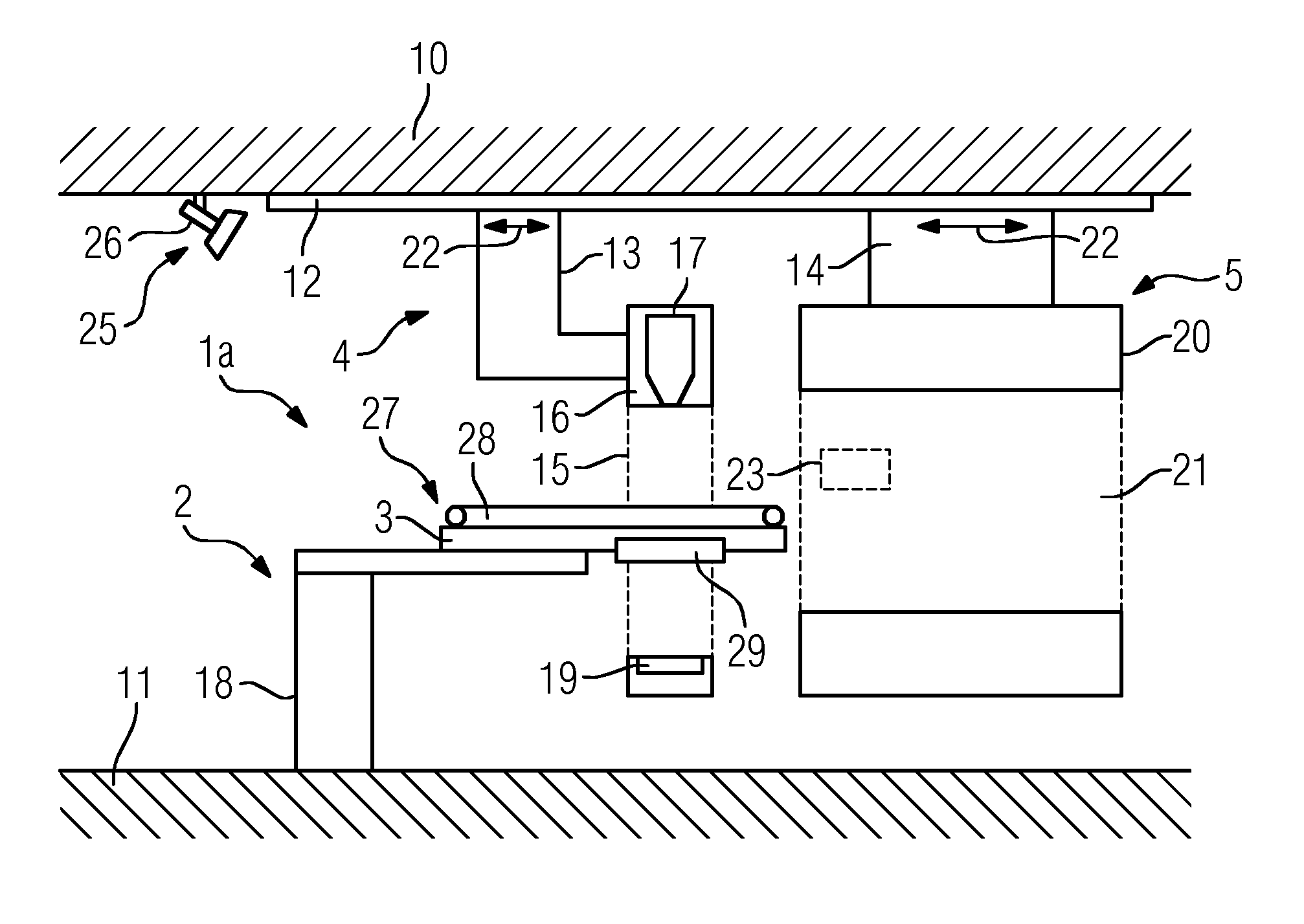
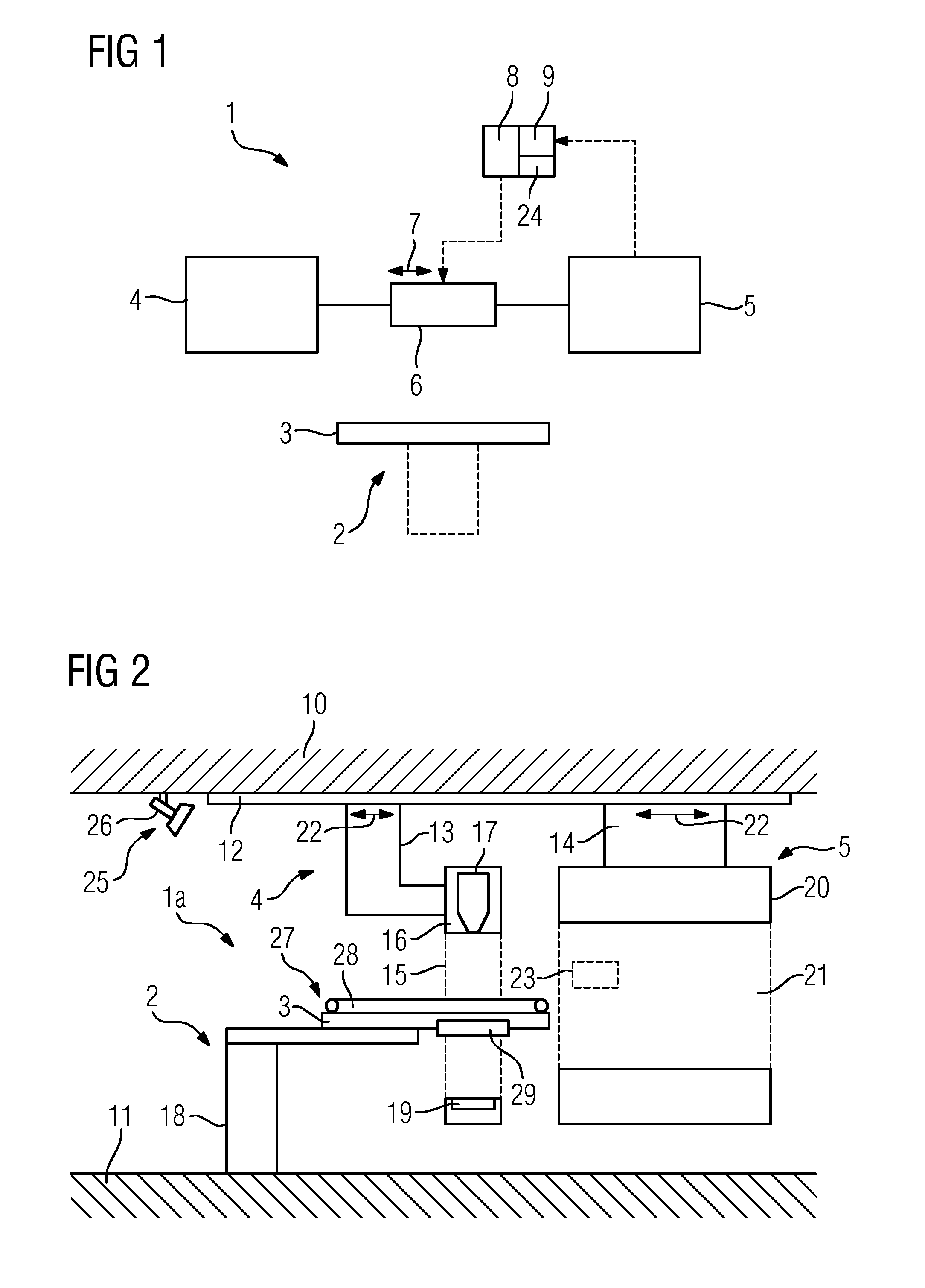
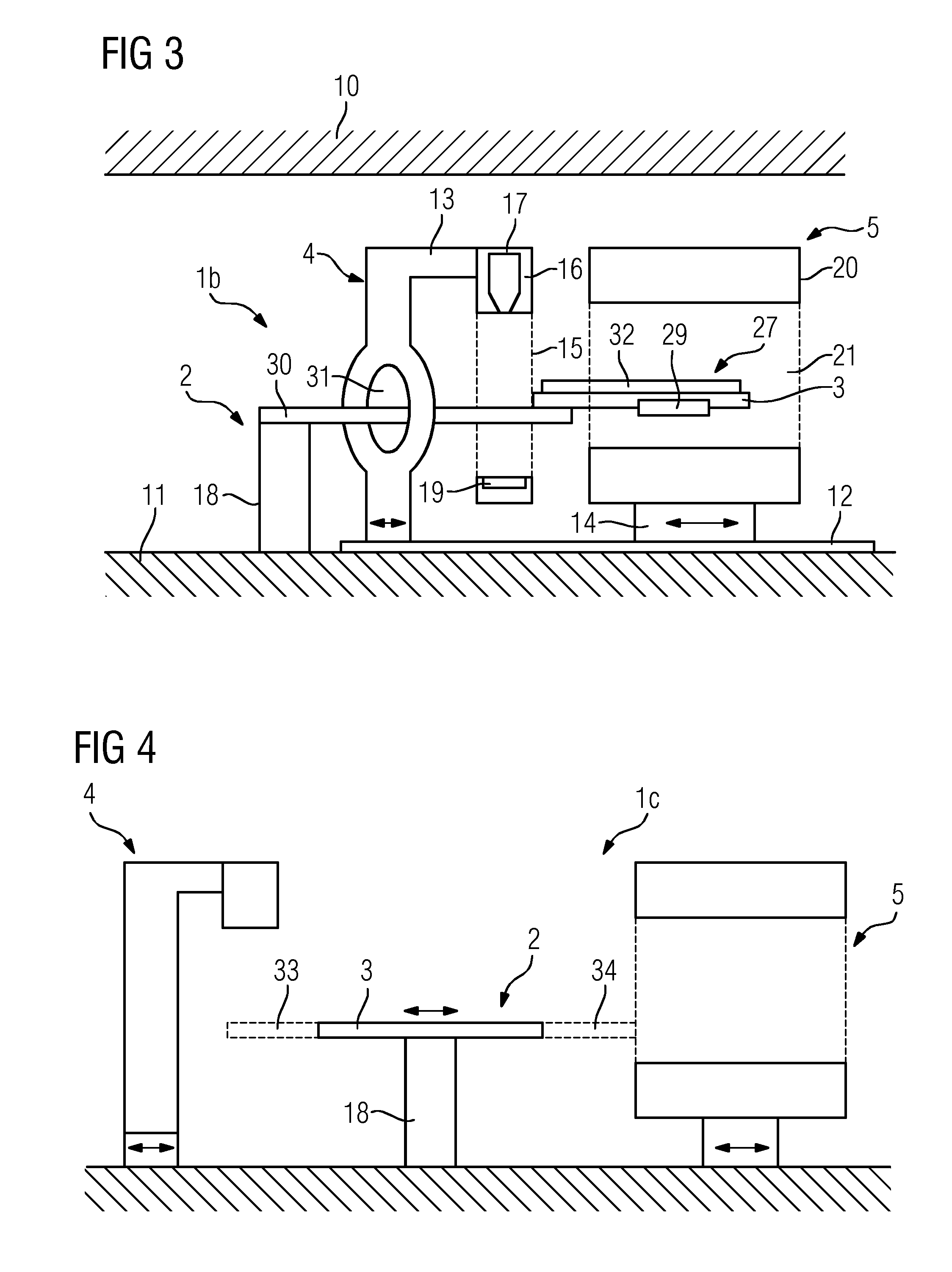
[0013]It is beneficial if the movement device comprises an in particular common means of guidance for the irradiation device and the image acquisition device. A rail guidance system in which the two subsystems are guided lends itself as particularly suitable in this regard. The guidance system is arranged on the ceiling and / or on the floor of a room containing the radiotherapy treatment device. In particular devices suspension-mounted by means of the guidance system and guided along a ceiling have the advantage that the floor area can be kept largely free for other activities, for example for access to the patient and for the placement of further devices.
[0014]A beneficial development of the treatment device in this connection furthermore provides that the linear guidance system extends along a longitudinal axis of the patient positioning platform of the patient positioning device. Such a solution presents itself as particularly attractive since in irradiation devices the irradiation head can in most cases be moved around the patient, in particular on a circular trajectory, and consequently a corresponding guidance device is present for the irradiation head, which is frequently arranged on a gantry. This can then simply be driven over or around the patient positioning platform or moved further away from the latter, while many image acquisition devices also comprise annular components at least partially encircling the patient positioning platform during the imaging, for example a gantry in the case of a computed tomography device or the main magnet array in the case of a magnetic resonance device. Linear guidance systems along a particular direction can furthermore be realized in a particularly simple manner.
[0015]Basically it should be noted that guidance systems of said type for medical equipment, including devices having a relatively great weight, are in principle already well-known in the prior art, such that the corresponding knowledge can also be applied to the present treatment device. For example, image acquisition devices have been proposed which can be maneuvered by way of such a guidance system during an operation toward a patient and away from the patient again, and the like.
[0016]The movement range of the image acquisition device and / or the irradiation device between the irradiation position and the image acquisition position can amount to between 10 cm and 200 cm. It has been demonstrated that traversing distances in the range from 10 cm up to 2 m should normally suffice for irradiation tasks in the region of the head, chest, lung, liver and prostate. Even when a magnetic resonance device is used, an adequate distance in order to minimize the interaction between the subsystems can already be achieved with such ranges of movement.

Problems solved by technology

This is why in practice irradiations, of the prostate for example, are performed with a considerable safety margin, which results in substantially the entire organ being irradiated, which can lead to undesirable side effects.
On the other hand, soft tissue resolution in particular and also three-dimensional imaging capability are severely limited in the case of X-ray devices, with the result that combination systems composed of magnetic resonance devices and irradiation devices including a linear accelerator have also been proposed.
The solutions described in each of the cited publications necessitate large-scale changes to the magnetic resonance configuration and are accompanied by limitations in terms of image quality and enormous costs for the radiotherapy treatment device.
Consequently the performance of the devices, the range of applications and patient comfort are frequently severely restricted.
The image acquisition device is in this case arranged at a distance, with the result that acquiring an image of the irradiation target at this moment in time is no longer possible.

Method used


Image

  • Radiotherapy treatment device comprising image acquisition device and irradiation device, and radiotherapy method
  • Radiotherapy treatment device comprising image acquisition device and irradiation device, and radiotherapy method
  • Radiotherapy treatment device comprising image acquisition device and irradiation device, and radiotherapy method

Examples


Embodiment Construction

[0041]FIG. 1 illustrates the basic principle of a radiotherapy treatment device 1. This comprises a patient positioning device 2 having a patient positioning platform 3. The patient positioning platform 3 and therefore the patient ideally immobilized thereon are kept motionless during an entire radiation therapy treatment. The radiotherapy treatment device 1 further comprises two essentially independent subsystems, namely a treatment device 4 and an image acquisition device 5. These can be displaced linearly via a movement device 6, as indicated by the arrow 7, relative to the patient positioning platform 3, in this case in the longitudinal direction thereof, so that in an image acquisition position the image acquisition device 5 is moved toward the patient such that an image acquisition can take place, and in a treatment position the treatment device 4 can be directed to a treatment target in the patient. In the present case the movement of the image acquisition device 5 is coupled...


PUM


Abstract

A radiotherapy treatment device comprising an image acquisition device, in particular a magnetic resonance device, an irradiation device comprising in particular a linear accelerator, and a patient positioning device having a patient positioning platform, wherein a movement device is provided for jointly moving the image acquisition device and the irradiation device between an irradiation position, in which a radiotherapeutic treatment of a patient located on the patient positioning platform is possible by means of the irradiation device, and an image acquisition position, in which an image acquisition of the patient located on the patient positioning platform is possible by means of the image acquisition device is provided. A radiotherapy method for treating an irradiation target in a patient by means of such a radiotherapy treatment device is also disclosed.

Description

CROSS-REFERENCE TO RELATED APPLICATIONS[0001]This application claims priority to DE Application No. 102013205211.1, having a filing date of Mar. 25, 2013, the entire contents of which are hereby incorporated by reference.FIELD OF TECHNOLOGY[0002]The following relates to a radiotherapy treatment device comprising an image acquisition device, in particular a magnetic resonance device, an irradiation device comprising in particular a linear accelerator, and a patient positioning device having a patient positioning platform. The following relates in addition to a radiotherapy method for treating an irradiation target in a patient by means of such a radiotherapy treatment device.BACKGROUND[0003]Radiation therapy is already widely known in the prior art. It finds application principally in the treatment of cancerous diseases, whereby accelerated particles are emitted in a targeted manner in such a way that they deposit the majority of their energy in an irradiation target, in particular a...

Claims


Application Information

Patent Timeline
Patent Type & Authority Patents(United States)
IPC IPC(8): A61N5/10
CPCA61N5/1049A61N2005/1055A61N2005/1063
Inventor GROSS, PATRICKHAUSOTTE, ANNEMARIEHEISMANN, BJORNSCHMIDT, SEBASTIAN
Owner SIEMENS HEALTHCARE GMBH
Why Eureka
Try Eureka