Light guide structure having axial-light blocking reflector

a technology of light guide structure and reflector, which is applied in the direction of fibre light guide, lighting and heating apparatus, instruments, etc., can solve the problems of not being able to achieve the desired light-emitting effect, not being able to easily put to practical use with good, and being concentrated in the emission of led light source, etc., to achieve the effect of high market competitiveness

Active Publication Date: 2015-12-29
D-LINK
View PDF11 Cites 0 Cited by
  • Summary
  • Abstract
  • Description
  • Claims
  • Application Information

AI Technical Summary

Benefits of technology

[0005]In view of the fact that a breakthrough in the design of indicator lamps for electronic devices is unattainable due to limitations imposed by the light-emitting properties, light-emitting effects, and costs of the light sources to be used, the inventor of the present invention put years of practical experience in the industry into repeated trials and improvements and finally succeeded in developing a light guide structure for guiding light broadly as disclosed herein. The present invention is intended for guiding light in a low-cost manner in which a single light-emitting element is used as the light source and is enabled not only to imitate the broad light-emitting effect of a plurality of light-emitting elements used together, but also to provide uniform light emission, allowing a designer to design electronic devices of variegated visual effects and hence of high market competitiveness.
[0006]It is an object of the present invention to provide a light guide structure for guiding light broadly. The light guide structure is installed in a housing of an electronic device and corresponds in position to a hollowed-out portion or a light-permeable portion of the housing. The light guide structure includes a conical light guide element and a partially blocking reflective element. The conical light guide element is a hollow cone and has an inner surface configured as a reflective surface for reflecting light. A light-emitting element (e.g., an LED) is provided in the conical light guide element and is adjacent to the pointed end of the conical light guide element. The other end (hereinafter referred to as the second end) of the conical light guide element is an opening corresponding in position to the hollowed-out portion or the light-permeable portion of the housing. The partially blocking reflective element is installed at the second end of the conical light guide element, covers the opening, and includes at least one light-permeable region and at least one opaque reflective region. The at least one opaque reflective region corresponds in position to the optical axis of the light-emitting element. The at least one light-permeable region, on the other hand, is located around the at least one opaque reflective region and is outside the optical axis of the light-emitting element. After the light emitted by the light-emitting element passes through the conical light guide element, a portion of the light penetrates the at least one light-permeable region, and the remaining portion of the light is reflected back into the conical light guide element by blocked reflection of the at least one opaque reflective region and is then reflected to the partially blocking reflective element by conical reflection of the reflective surface. Thus, the aforesaid remaining portion of the light emitted by the light-emitting element undergoes the blocked reflection and the conical reflection repeatedly until it is projected to and penetrates the at least one light-permeable region and propagates out of the housing through the hollowed-out portion or the light-permeable portion. Thanks to the repeated reflection feature of the light guide structure, all the light emitted by the light-emitting element will be guided to the at least one light-permeable region, thereby effectively increasing the range of light projection. This allows the broad light-emitting effect of a plurality of light-emitting elements used together to be simulated by a single light-emitting element, and production costs can hence be effectively reduced. In addition, as a single light-emitting element is used as the light source in the present invention to simulate the broad light-emitting effect of multiple light-emitting elements, uneven light emission which may otherwise result from the use of multiple light-emitting elements, or more particularly from the differences in their light emission efficiency, is avoided.

Problems solved by technology

While the aforesaid electronic device can be modified in design by changing the shapes or arrangement of the indicator lamps, not every design can be easily put to practical use with good results.
However, the light emitted by an LED light source is rather concentrated and can directly and effectively illuminate only a small area.
If a light-permeable or hollowed-out portion of the housing of an electronic device is of a shape encompassing a large area (e.g., an annular shape) or of a complicated shape, a single LED light source will be insufficient to provide the desired light-emitting effect, given the light-emitting properties and light-emitting capabilities of LED light sources in general.
Nevertheless, not only does this design incur higher production costs, but also uneven light emission may result and thus compromise the intended visual effect.
To solve the problem of uneven light emission, a light guide plate may be provided to guide the light emitted by a single light-emitting element to the target area, but this is not a cost-effective solution because light guide plates are typically used in the backlights of screens and are more expensive than most light-emitting elements.
Furthermore, existing solutions to the problem of uneven light emission often lead to a significant increase in production costs and consequently to low market competitiveness.
Apparently, the esthetic design of electronic devices has been limited to a large extent by the light-emitting properties, light-emitting effects, and costs of the light sources used.
These limiting factors have hindered designers' creativity and prevented an otherwise much greater variety of products from being produced, which is truly a shame.

Method used


Image

  • Light guide structure having axial-light blocking reflector
  • Light guide structure having axial-light blocking reflector
  • Light guide structure having axial-light blocking reflector

Examples


Embodiment Construction

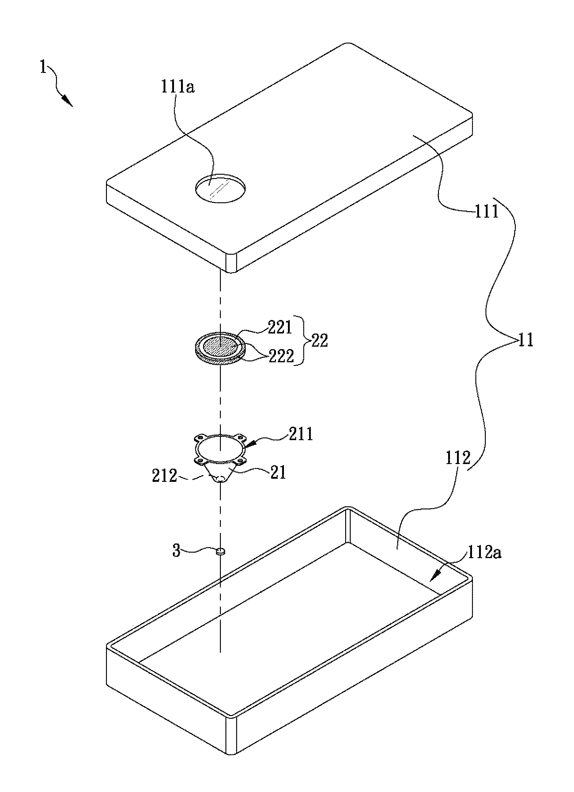
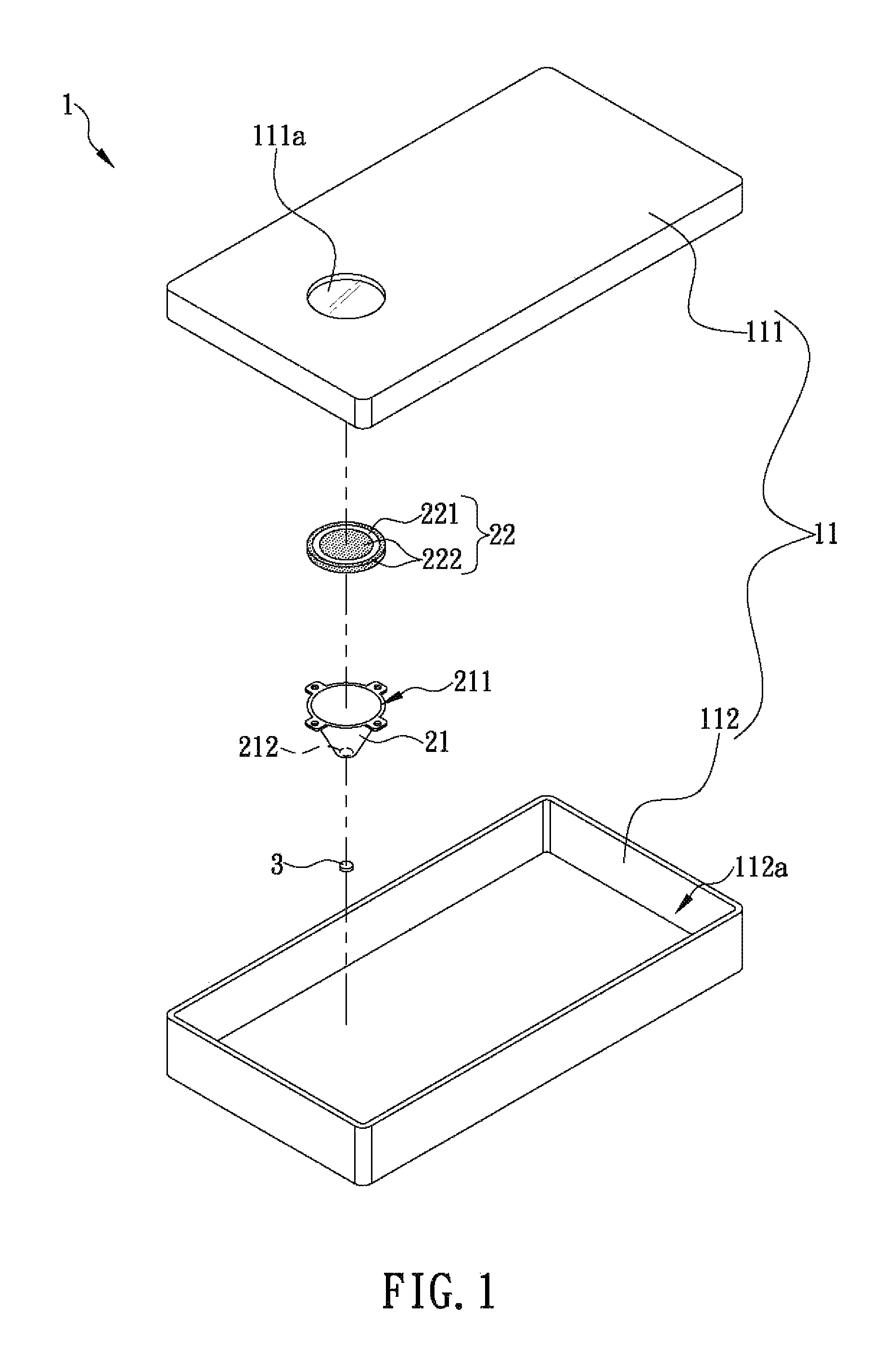
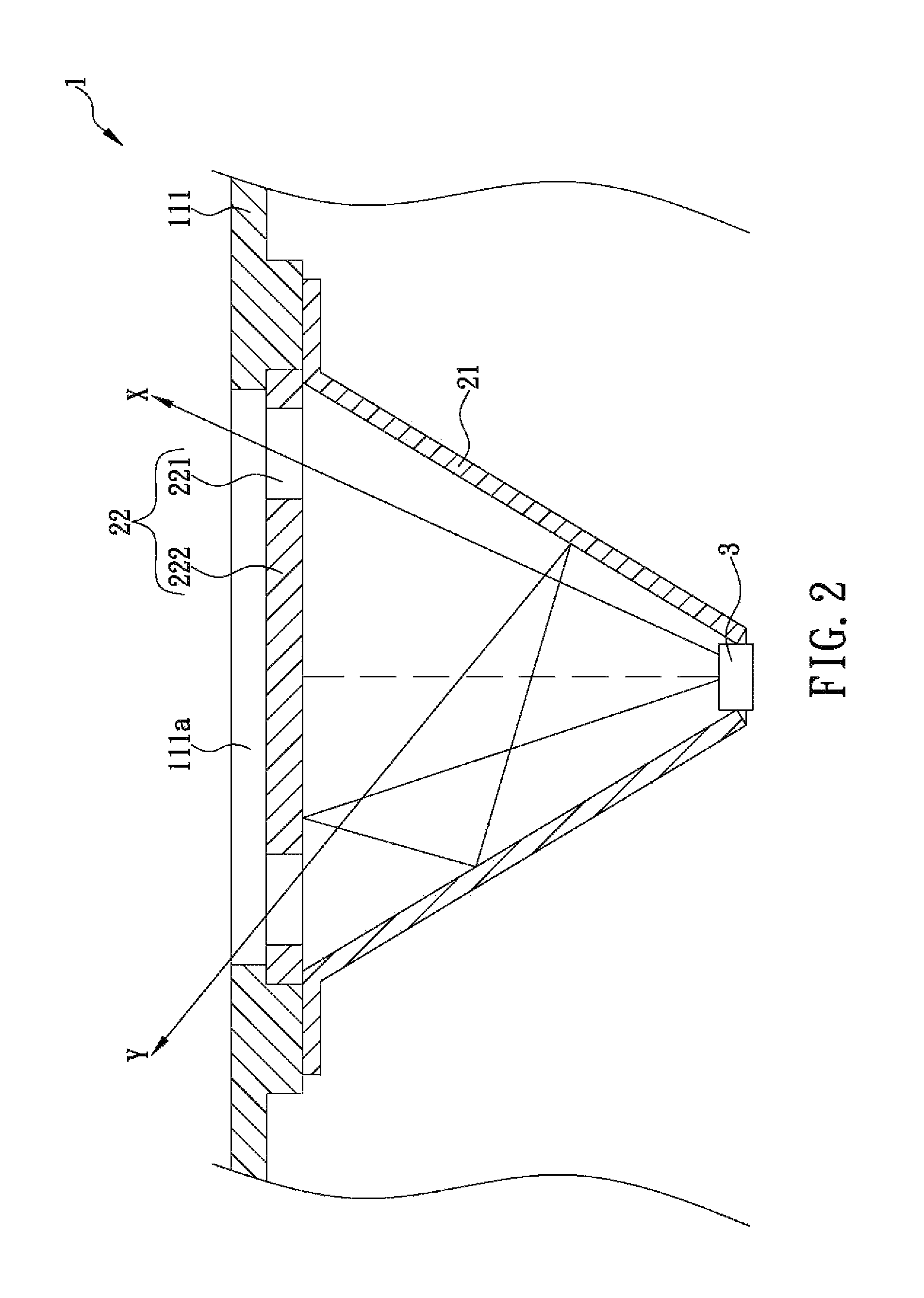
[0011]The present invention discloses a light guide structure for guiding light broadly. Referring to FIG. 1, the light guide structure according to the first preferred embodiment of the present invention is installed in a housing 11 of an electronic device 1 and corresponds in position to a light-permeable portion 111a (or a hollowed-out portion) of the housing 11. In the first preferred embodiment, the housing 11 is assembled from an upper housing member 111 and a lower housing member 112. The upper housing member 111 is provided with a round light-permeable portion 111a, and the light guide structure is installed at a position corresponding to the light-permeable portion 111a. The lower housing member 112, on the other hand, is provided with a receiving space 112a for receiving the light guide structure as well as a circuit board (not shown) and other components (not shown) of the electronic device 1. The formation and assembly method of the housing 11 are not major technical fea...


PUM


Abstract

A light guide structure including a conical hollow light guide element having reflective inner surface, a light-emitting element (e.g., an LED) provided in one end of the conical light guide element, and a reflective element covering an opening on the other end of the conical light guide element and including a light-permeable region and an opaque reflective region corresponding to an optical axis of the light-emitting element, with the light-permeable region is located around the opaque reflective region and outside the optical axis.

Description

FIELD OF THE INVENTION[0001]The present invention relates to a light guide structure, more particularly to a light guide structure for guiding light broadly, which has a repeated reflection feature capable of guiding all the light emitted by a light-emitting element to at least one light-permeable region, thereby effectively increasing the range of light projection and simulating a broad light-emitting effect of a plurality of light-emitting elements through using a single light-emitting element.BACKGROUND OF THE INVENTION[0002]Many electronic devices are equipped with light-emitting elements. Typically, the housing of such an electronic device has a light-permeable or hollowed-out portion, and a light-emitting element is provided at a position corresponding to the light-permeable or hollowed-out portion, thus allowing the light emitted by the light-emitting element to propagate out of the housing through the light-permeable or hollowed-out portion. In addition to serving as an indi...

Claims


Application Information

Patent Timeline
Patent Type & Authority Patents(United States)
IPC IPC(8): F21V13/04F21V8/00
CPCG02B6/0008
Inventor CHEN, I-HUNG
Owner D-LINK
Why Eureka
Try Eureka