Connector and mounting method therefor

a technology of connecting rods and mounting methods, which is applied in the direction of vehicle connectors, coupling parts mounting, coupling device connection, etc., can solve the problems of unavoidable clearance between the terminal fittings, terminal fitting shaking slightly in the cavity, and the connector mounted to the wiring harness installed in the vehicle is subject to vibration as the vehicle runs, so as to suppress the transmission of vibrations from the vibrating part, limit sliding movements, and suppress the shaking of the terminal fittings

Active Publication Date: 2016-01-05
SUMITOMO WIRING SYST LTD
View PDF19 Cites 4 Cited by
  • Summary
  • Abstract
  • Description
  • Claims
  • Application Information

AI Technical Summary

Benefits of technology

[0007]The invention relates to a connector to be mounted on an end of a wire to be installed in a vehicle. The connector has a housing and at least one terminal fitting accommodated in the housing. The terminal fitting is connected to the end of the wire, and the wire is drawn out from the housing. A bracket is provided for fixing the housing to a case of a device installed in the vehicle. The bracket includes a wire fixing portion for fixing the wire between the housing and a vibrating part that vibrates as the vehicle operates. More particularly, the wire fixing portion fixes a part of the wire that extends in a direction intersecting an extending direction of the wire in the vibrating part, thereby suppressing transmission of vibrations from the vibrating part to the connector. As a result, the wire fixing portion suppresses shaking of the terminal fitting in the housing and limits sliding movements between terminal fittings. Consequently, connection reliability is improved.
[0008]The wire fixing portion may fix the wire by tightening the wire. Thus, the wire can be fixed reliably to the wire fixing portion without being affected by the thickness of the wire and the transmission of vibration from the vibrating part to the wire draw-out part can be suppressed reliably. Further, it is not necessary to change the shape of the wire fixing portion according to the thickness and the like of the wire and it is possible to reduce a burden in parts management and manufacturing cost.
[0010]A cover may be attached to the bracket for covering and protecting the wire draw-out part of the housing. The wire fixing portion may be integral or unitary with the cover. Thus, transmission of vibration from the vibrating part to the wire draw-out part can be suppressed by the cover that protects the wire, thereby reducing manufacturing cost more than if the cover and the wire fixing portion were provided separately.
[0011]The cover may cover a part of the housing from the wire draw-out part to the wire fixing portion. Thus, the wire fixing portion and the wire are less likely to deteriorate due to exposure to the elements. Vibrations caused by a reduced fixing force resulting from a deteriorated wire fixing portion or a deteriorated wire are avoided.
[0012]The bracket may be fixed to the case by tightening at least one tightening member into the case, and the cover may be fixed to the case by being tightened together with the bracket by the tightening member. Accordingly, it is not necessary to provide a separate part for attaching the cover to the bracket. Further, the cover and the bracket can be assembled with the case by one tightening operation, thereby reducing the manufacturing cost and the number of operation steps for assembling the connector.
[0013]The bracket may include a mounting seat for attaching the cover to the bracket in advance before the bracket is attached to the case. Thus, the connector can be transported with the cover and the wire fixing portion attached to the bracket. As a result, parts management is more efficient and the connector is not likely to be damaged by the wire drawn out from the housing being caught by another member.

Problems solved by technology

A clearance is unavoidable between the terminal fitting and the inner wall of the cavity and hence the terminal fitting shakes slightly in the cavity.
A connector mounted to a wiring harness installed in a vehicle is subject to vibration as the vehicle runs.
As a result, sliding abrasion occurs between connecting parts of the terminal fittings and connection reliability is reduced.

Method used


Image

  • Connector and mounting method therefor
  • Connector and mounting method therefor
  • Connector and mounting method therefor

Examples


Embodiment Construction

[0034]A connector in accordance with a first embodiment of the invention is identified by the numeral 10 in FIGS. 1 to 10. The connector 10 is connected to ends of wires W1 to be arranged in a vehicle and to be mounted on a case (not shown) of a device in the vehicle.

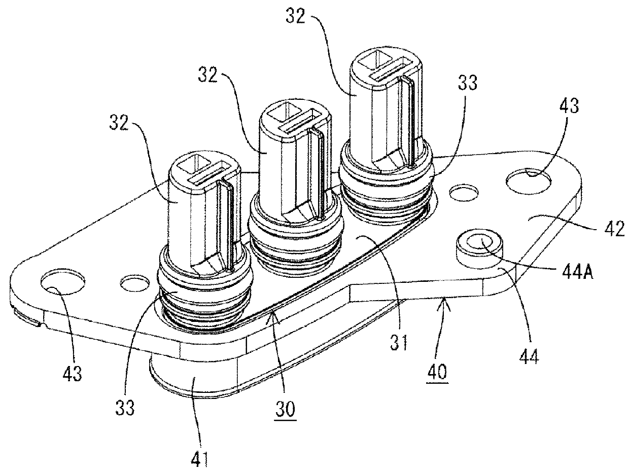
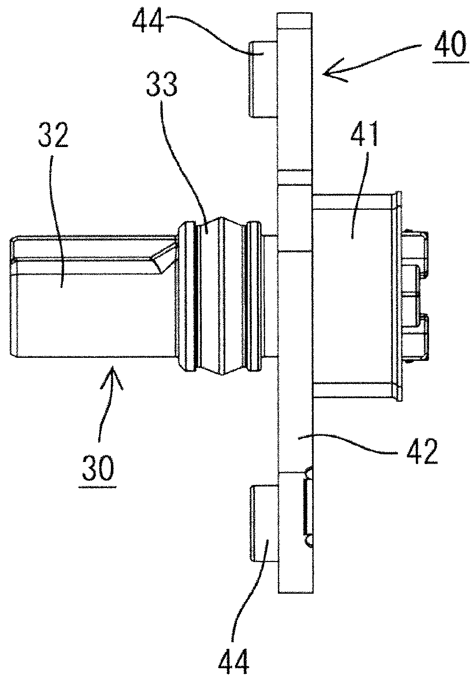
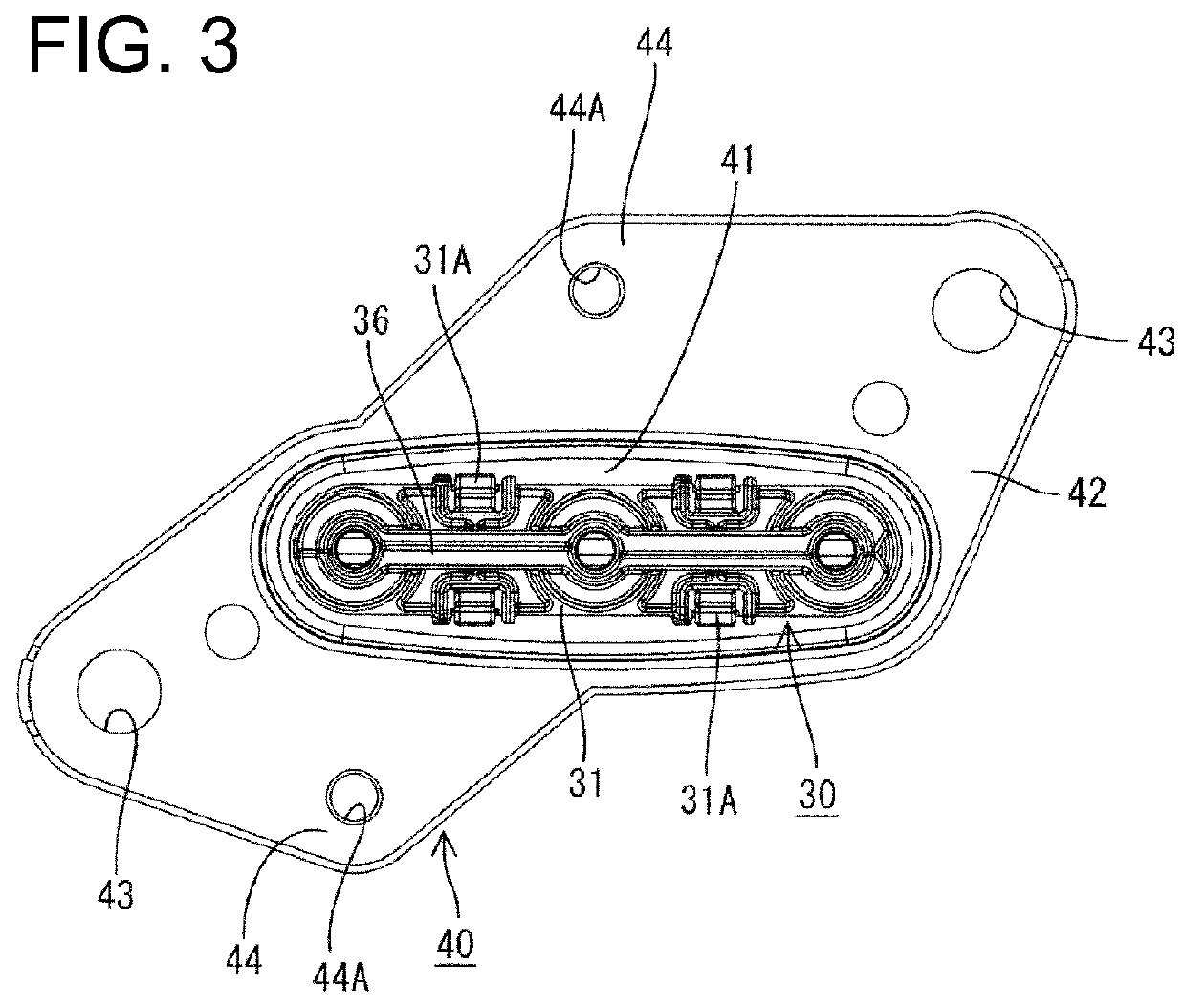
[0035]As shown in FIG. 10, the connector 10 includes female terminals 20 to be connected to the ends of the wires W1, a housing 30 made e.g. of synthetic resin to accommodate the female terminals 20, a shield bracket 40 made of conductive metal and configured to at least partly cover the housing 30 and a cover 50 made e.g. of synthetic resin and to be attached to the shield bracket 40. In the following description, reference to the vertical direction is based on FIGS. 2, 4 and 10, forward and backward directions are based on FIG. 10, and a side to be mounted on the case of the device (shown right side in FIG. 10) is referred to as the front.

[0036]The wires W1 are covered by a covering member W2, as shown in FIGS. 7, and...


PUM


Abstract

A connector (10) to be mounted on ends of wires (W1) to be installed in a vehicle includes female terminals (20) that are to be connected to the ends of the wires, a housing (30) in which the female terminals (20) are accommodated and from which the wires (W1) are drawn out, and a shield bracket (40) that fixes the housing (30) to a case of a device installed in the vehicle. The shield bracket (40) includes a wire fixing portion (54) between a wire draw-out part (P1) where the wires (W1) are drawn out from the housing (30) and a vibrating part (P2). The wire fixing portion (54) fixes the wires (W1) extending in a direction intersecting an extending direction of the wires (W1) in the vibrating part (P2) where the wires (W1) vibrate as the vehicle vibrates.

Description

BACKGROUND OF THE INVENTION[0001]1. Field of the Invention[0002]The invention relates to a connector.[0003]2. Description of the Related Art[0004]U.S. Pat. No. 5,997,349 discloses a connector to be mounted on an end of a wire. This connector includes a terminal fitting connected to the end of the wire and a housing formed with a cavity. The terminal fitting is fit into the cavity from behind. The housing has a front stop to limit forward movement of the terminal into the housing and a locking lance to retain the terminal fitting in the housing.[0005]A clearance is unavoidable between the terminal fitting and the inner wall of the cavity and hence the terminal fitting shakes slightly in the cavity. A connector mounted to a wiring harness installed in a vehicle is subject to vibration as the vehicle runs. Thus, terminal fittings shake in forward and backward directions in the cavity even after the connector is connected to a mating connector. As a result, sliding abrasion occurs betwe...

Claims


Application Information

Patent Timeline
Patent Type & Authority Patents(United States)
IPC IPC(8): H01R13/58H01R13/74H01R13/516H01R13/533
CPCH01R13/5804H01R13/5837H01R13/748H01R2201/26
Inventor SAKAKURA, KOUJI
Owner SUMITOMO WIRING SYST LTD
Why Eureka
Try Eureka