Boomerang link with vibration filtering ability and aircraft engine mount provided with such link

a technology of vibration filtering ability and boom link, which is applied in the direction of aircraft, power plant arrangement/mounting, transportation and packaging, etc., can solve the problems of reducing the comfort of passengers, affecting the safety of passengers, and affecting the transmission of vibrations from the jet engine, so as to achieve the effect of simple, economical and effectiv

Active Publication Date: 2016-01-19
AIRBUS OPERATIONS (SAS)
View PDF10 Cites 5 Cited by
  • Summary
  • Abstract
  • Description
  • Claims
  • Application Information

AI Technical Summary

Benefits of technology

[0016]A notable object of the invention is to provide a simple, economical and effective solution to this problem.
[0025]Such flexibility or elasticity enables the boomerang link to filter any relative vibrations of connecting members mounted in respective aforementioned orifices of the boomerang link as well as supporting loads liable to be applied to this boomerang link.
[0039]The aforementioned boomerang link makes it possible to enable the engine mount to filter any vibrations of the third connecting member relative to the second connecting member. Such vibrations can in fact be transmitted to the third connecting member by an aircraft engine connected to the latter connecting member.
[0047]The rigid boomerang link makes it possible to absorb transverse forces having an intensity above a predetermined threshold, as will emerge more clearly hereinafter.
[0050]When said engine mount comprises at least one flexible boomerang link and at least one rigid boomerang link as described above, said flexible and rigid boomerang links are advantageously conformed so that said flexible boomerang link maintains a clearance between said third connecting member and said rigid boomerang link when the transverse forces applied to said engine mount are at a level below a predetermined threshold and so that said third connecting member comes into abutment in said third orifice of said rigid boomerang link thanks to sufficient deformation of said flexible boomerang link when said transverse forces are at a level above said predetermined threshold.
[0054]This configuration therefore makes it possible to facilitate understanding and control of the mechanical behavior of the engine mount in the event of extreme forces, this control being necessary to satisfy regulatory requirements, as well as benefiting from the flexibility of each flexible boomerang link both in normal operation and in the event of blade loss.

Problems solved by technology

However, the connection of the jet engine 10 to the pylon 12 by means of the components described above leads to transmission of vibrations from the jet engine to the pylon 12.
This is particularly problematic in the case of propulsion systems attached to the fuselage of the aircraft, as described above, because the vibrations are then transmitted directly to the structure of the fuselage.
These vibrations are therefore liable to increase the wear of the structure of the fuselage and to reduce the comfort of passengers.
In these latter propulsion systems, vibrations induced by the jet engines are in theory damped by the flexibility of the wings.
However, if the intensity of these vibrations is particularly high, notably in the event of a malfunction of a jet engine, there is also a risk of the vibrations of the latter being transmitted to the structure of the fuselage of the aircraft.

Method used


Image

  • Boomerang link with vibration filtering ability and aircraft engine mount provided with such link
  • Boomerang link with vibration filtering ability and aircraft engine mount provided with such link
  • Boomerang link with vibration filtering ability and aircraft engine mount provided with such link

Examples


second embodiment

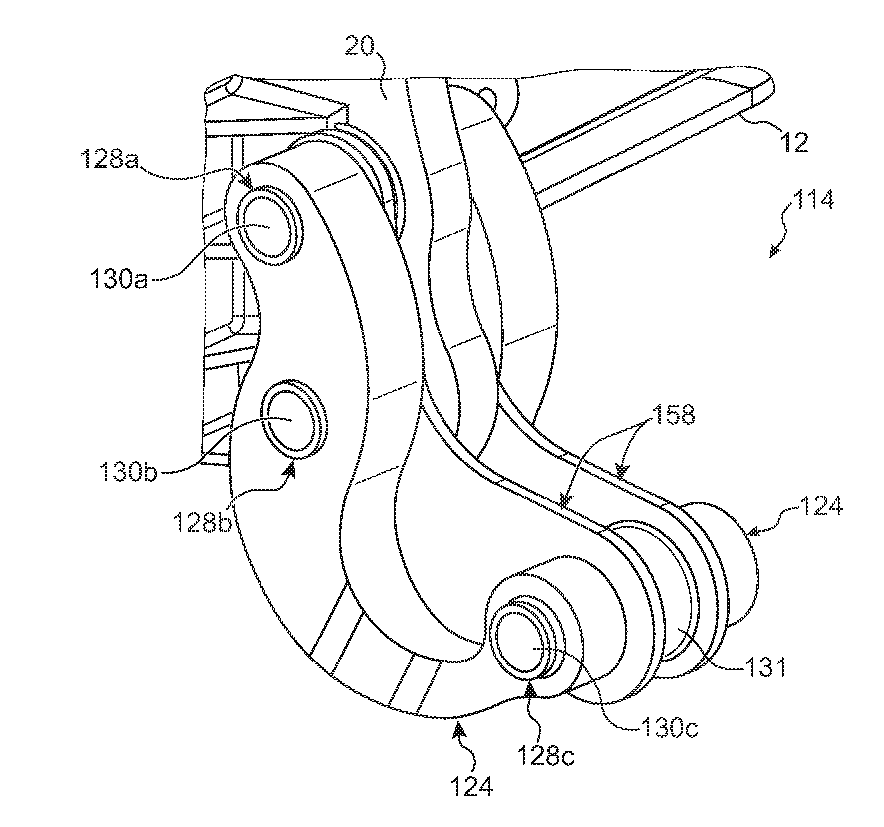
[0095]FIG. 6 shows the invention in which the engine mount 114 further includes a mechanical energy dissipating device or damper 152 connecting together the second and third connecting members 128b, 128c.

[0096]The damper 152, represented very schematically, has a first longitudinal end 154 pivotably mounted on the second connecting member 128b and a second longitudinal end 156 pivotably mounted on the third connecting member 128c. The damper 152 therefore has a working axis W passing through the respective axes 134b, 134c of the second and third orifices 132b, 132c of each boomerang link 124.

[0097]This damper 152 may be of any appropriate conventional type, for example of the hydraulic, hydropneumatic, magneto-rheologic or other type.

[0098]Generally speaking, the damper 152 enables dissipation of at least sonic of the kinetic energy related to any vibrations between the second and third connecting members 128b, 128c.

[0099]Alternatively, the damper 152 may be fixed directly to one ...

third embodiment

[0101]FIG. 7 shows the invention in which each boomerang link 124, referred to as a “flexible boomerang link” is associated with another boomerang link 158, referred to as a “rigid boomerang link”, also visible in FIG. 8.

[0102]Each rigid boomerang link 158 includes a first orifice 132a′ and a second orifice 132b′ (FIG. 8) in which the first and second connecting members 128a, 128b, respectively, are mounted with a close fit.

[0103]Each rigid boomerang link 158 also includes a third orifice 132c′ in which the third connecting member 128c is mounted with a clearance j.

[0104]FIG. 8 notably shows the rigid boomerang link 158 in section on a plane orthogonal to the respective axes 134a′, 134b′, 134c′ of the orifices of this rigid boomerang link, which are respectively superposed on the axes 134a, 134b, 134c, respectively, of the orifices of the corresponding flexible boomerang link 124.

[0105]As this FIG. 8 shows, a first straight line segment T′ extending from the axis 134a′ of the first ...


PUM


Abstract

A boomerang link for aircraft engine mounts, including a first orifice and a second orifice both designed to connect the boomerang link to an aircraft pylon, and a third orifice designed to connect the boomerang link to an aircraft engine. The third orifice is offset relative to a plane passing simultaneously through an axis of the first orifice and through an axis of the second orifice. When the boomerang link is seen in section in any plane orthogonal to the axes, a straight line segment extending from the axis of the second orifice to an axis of the third orifice crosses a region external to the boomerang link. This conformation confers on the boomerang link a flexibility enabling it to filter transverse vibrations between an engine and an aircraft pylon.

Description

CROSS-REFERENCES TO RELATED APPLICATIONS[0001]This application claims the benefit of the French patent application No. 1262951 filed on Dec. 28, 2012, the entire disclosures of which are incorporated herein by way of reference.BACKGROUND OF THE INVENTION[0002]The present invention concerns a boomerang link for aircraft engine mounts.[0003]It also concerns an engine mount including such a link, a propulsion system including such an engine mount, and an aircraft equipped with such a propulsion system,[0004]Aircraft jet engines are usually attached to the wings or to the fuselage by means of a pylon to which the jet engine is connected by means of engine mounts and links for transmitting thrust forces.[0005]FIG. 1 shows an example of a propulsion system 8 of the type designed to be attached laterally to an aircraft fuselage rear part. This propulsion system 8 includes a jet engine 10, for example of the open rotor pusher type, and a pylon 12, partially visible, to which the jet engine ...

Claims


Application Information

Patent Timeline
Patent Type & Authority Patents(United States)
IPC IPC(8): B64C27/26B64D27/26B64D27/00
CPCB64D27/26B64D27/00B64D2027/266
Inventor BROCHARD, WOLFGANGTERRAL, ROMAIN
Owner AIRBUS OPERATIONS (SAS)
Why Eureka
Try Eureka