
Gauge having variable display

a variable display and gauge technology, applied in the field of gauges, can solve the problems of limiting the amount of information that may be displayed on the scale, reading provided by the gauge may have a margin of error, etc., and achieve the effects of improving the viewing of the gauge, and reducing the size of the gaug

Active Publication Date: 2016-01-26
CONTINENTAL AUTOMOTIVE SYST INC
View PDF16 Cites 2 Cited by
  • Summary
  • Abstract
  • Description
  • Claims
  • Application Information

AI Technical Summary

Benefits of technology

The present invention provides a gauge that has more space in the dial, which results in a cleaner design and improved visibility. The dial is positioned closer to the lens, making it easier to see from different angles. Compared to typical gauges, the present invention has fewer parts, reducing costs. Additionally, the present invention is shorter in length, which makes it easier to meet packaging requirements.

Problems solved by technology

The reading provided by the gauge may have a margin of error when viewed from various angles.
Also, the pointer takes up space on the front of the gauge, which limits the amount of information that may be displayed on the scale.

Method used


Image

  • Gauge having variable display
  • Gauge having variable display
  • Gauge having variable display

Examples


Embodiment Construction

[0021]The following description of the preferred embodiment(s) is merely exemplary in nature and is in no way intended to limit the invention, its application, or uses.

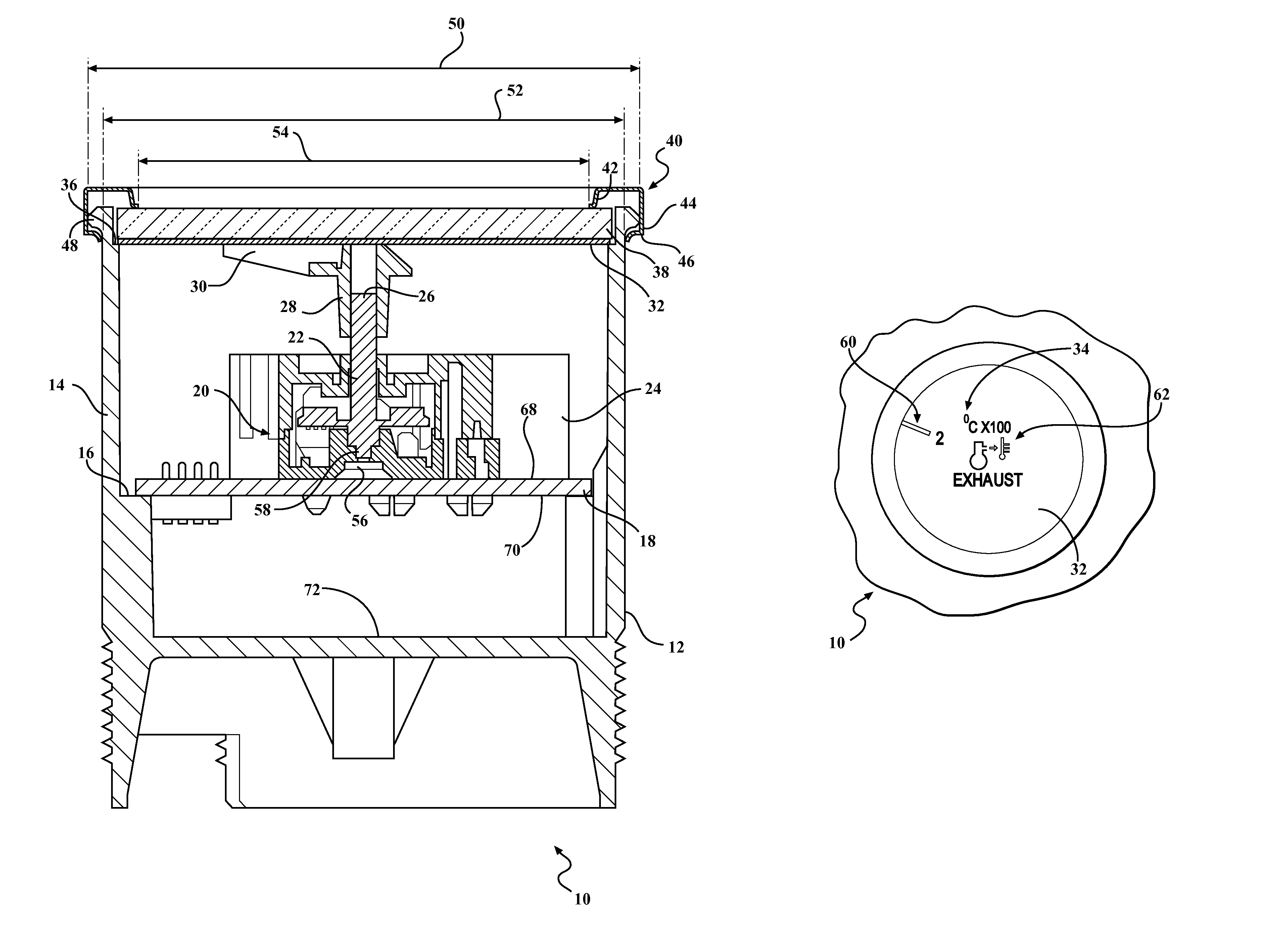
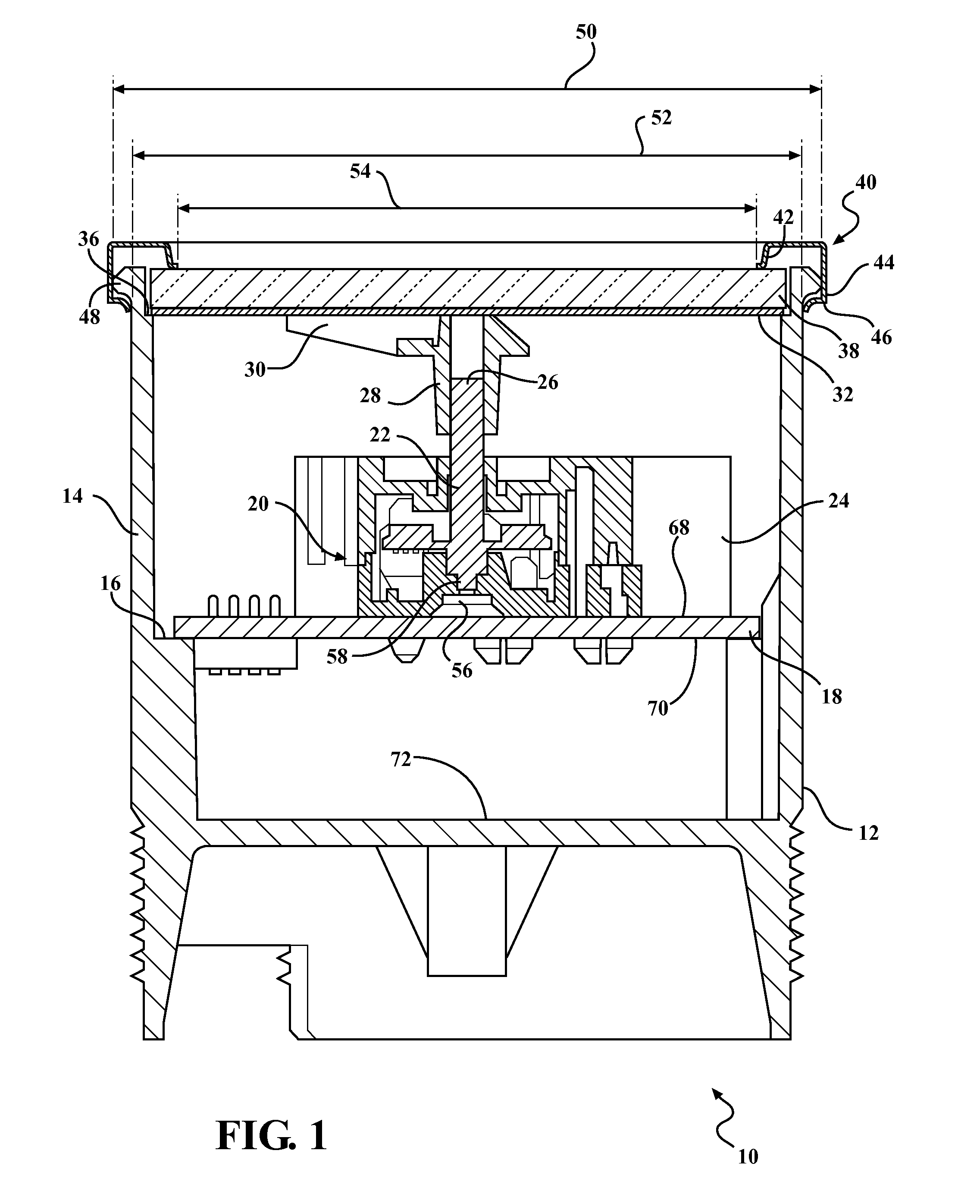
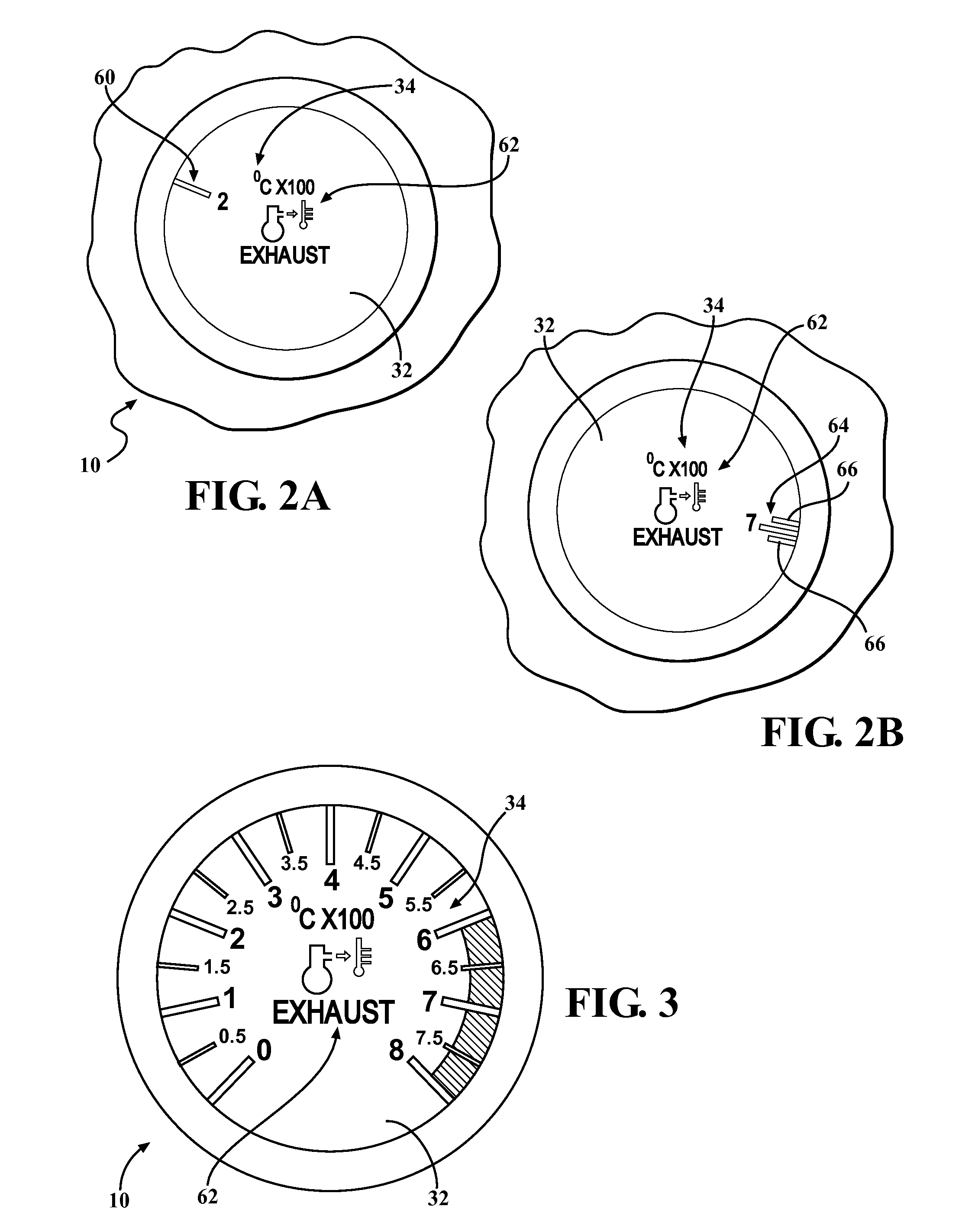
[0022]An embodiment of a gauge according to the present invention is shown in FIGS. 1-4, generally at 10. The gauge 10 includes a housing 12 having an outer sidewall 14. Formed as part of the sidewall 14 is a ledge portion 16, and mounted on the ledge portion 16 is a printed circuit board (PCB) 18. Mounted on the PCB 18 is various circuitry necessary for the operation of the gauge 10, as well as an actuator, shown generally at 20, which in this embodiment is a stepper motor. However, it is within the scope of the invention that other types of actuators may be used.

[0023]The stepper motor 20 includes various components which are used for rotating a shaft 22, and the shaft 22 protrudes outwardly away from the stepper motor housing 24. Mounted on an end 26 of the shaft 22 is a tube portion 28, and connected to the tube p...


PUM


Abstract

A gauge which uses a prism or other type of reflector to illuminate a single graphic or icon on a dial such that only one graphic on the dial is shown during the operation of the gauge. All of the remaining graphics have a dead front appearance, and cannot be viewed, such that the gauge presents only one discrete value at a time. The dial is beneath a lens, and the prism is beneath the dial. An actuator is mounted to a PCB, and an LED is also mounted to the PCB to allow the prism to transmit light to the desired area of the dial. The dial also includes a central graphic, or icon, and the gauge is able to display different values, while the central graphic remains constantly illuminated in the center of the gauge.

Description

FIELD OF THE INVENTION[0001]The invention relates generally to a gauge having a dial with several graphics, where only one of the graphics is illuminated at a time, while the remainder of the graphics have a dead front appearance.BACKGROUND OF THE INVENTION[0002]Gauges are commonly used in different applications to convey information to a driver about various operating conditions of a vehicle. Several gauges may be included as part of an instrument cluster to provide information to the driver relating to vehicle speed, engine speed, amount of fuel used, engine temperature, fuel economy, and the like. Gauges are also used for applications other than for automotive use, such as air compressors, boilers, and the like. When used in a vehicle, typical gauges receive information from a device such as the vehicle's electronic control unit (ECU). These gauges include a pointer which rotates and aligns with various portions of a scale, and the pointer moves to various locations along the sca...

Claims


Application Information

Patent Timeline
Patent Type & Authority Patents(United States)
IPC IPC(8): G01D11/28G01D13/02G01D13/04G01D13/12
CPCG01D13/20G01D13/265B60K2360/698G01D13/04G01D11/28
Inventor FERNANDEZ, MICHEL, MARCELA
Owner CONTINENTAL AUTOMOTIVE SYST INC
Learn More