Capacitor fastening

a technology of capacitors and fastening methods, applied in the direction of manufacturing tools, coupling device connections, branching pipes, etc., can solve the problems of high manufacturing tolerance of capacitors, difficult fastening of cylindrical capacitors, and time-consuming

Active Publication Date: 2016-01-26
ABB (SCHWEIZ) AG
View PDF19 Cites 7 Cited by
  • Summary
  • Abstract
  • Description
  • Claims
  • Application Information

AI Technical Summary

Benefits of technology

[0017]In an exemplary embodiment of the disclosure, capacitors with bottom screws are not needed and hence there are fewer parts to be mounted. In addition, all mounting works can be carried out from one direction without having to turn and rotate the capacitor system. Moreover, increased useful space is gained in the modules where the capacitors are placed, and the space can be utilized for larger capacitance or by using fewer capacitors of high capacitance, thus allowing cost savings. For example, when a capacitor with 20% more volume is used instead of a 100 mm high capacitor, four capacitors from a set of 20 may be left out. A capacitor without bottom screws can be less expensive, which allows capacitance to be increased by 20% at the same cost.

Problems solved by technology

Cylindrical capacitors, for example, can be difficult to fasten because their geometry usually does not contain actual fastening features.
Another issue can arise from high manufacturing tolerances of capacitors.
From the point of view of mounting, the above fastening methods can be difficult and time-consuming.
Many fastenings may be needed, whereby volume of the mounting space is wasted.

Method used


Image

  • Capacitor fastening
  • Capacitor fastening
  • Capacitor fastening

Examples


Embodiment Construction

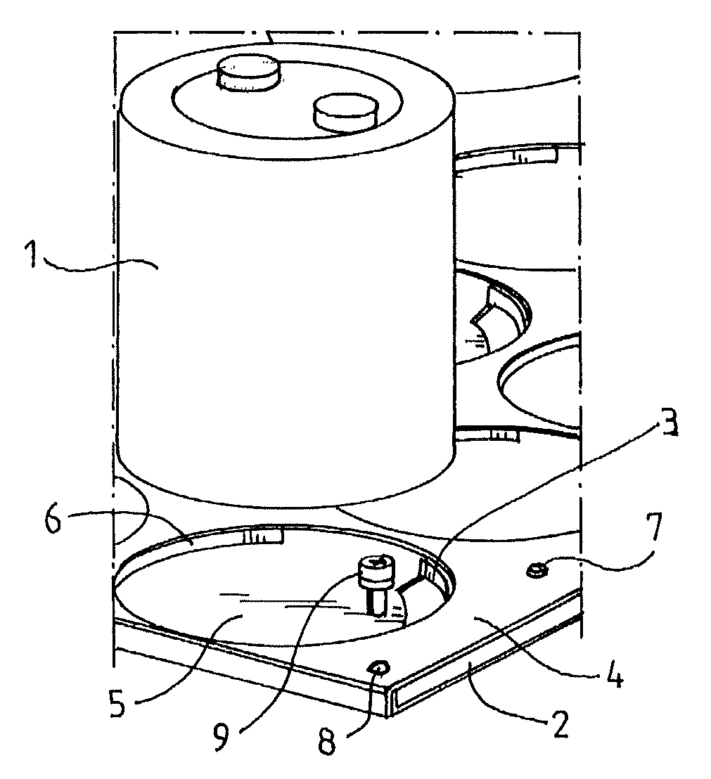
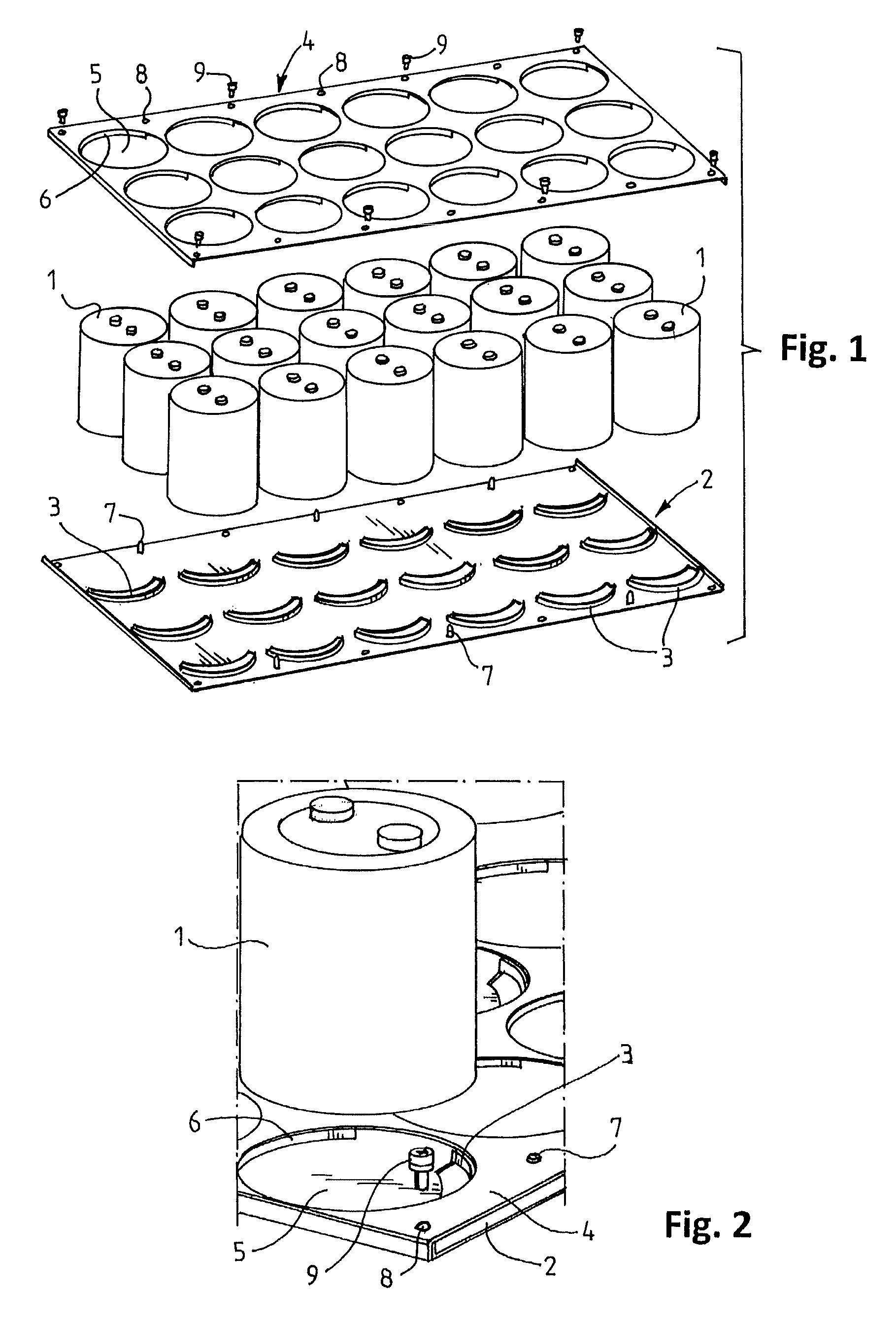
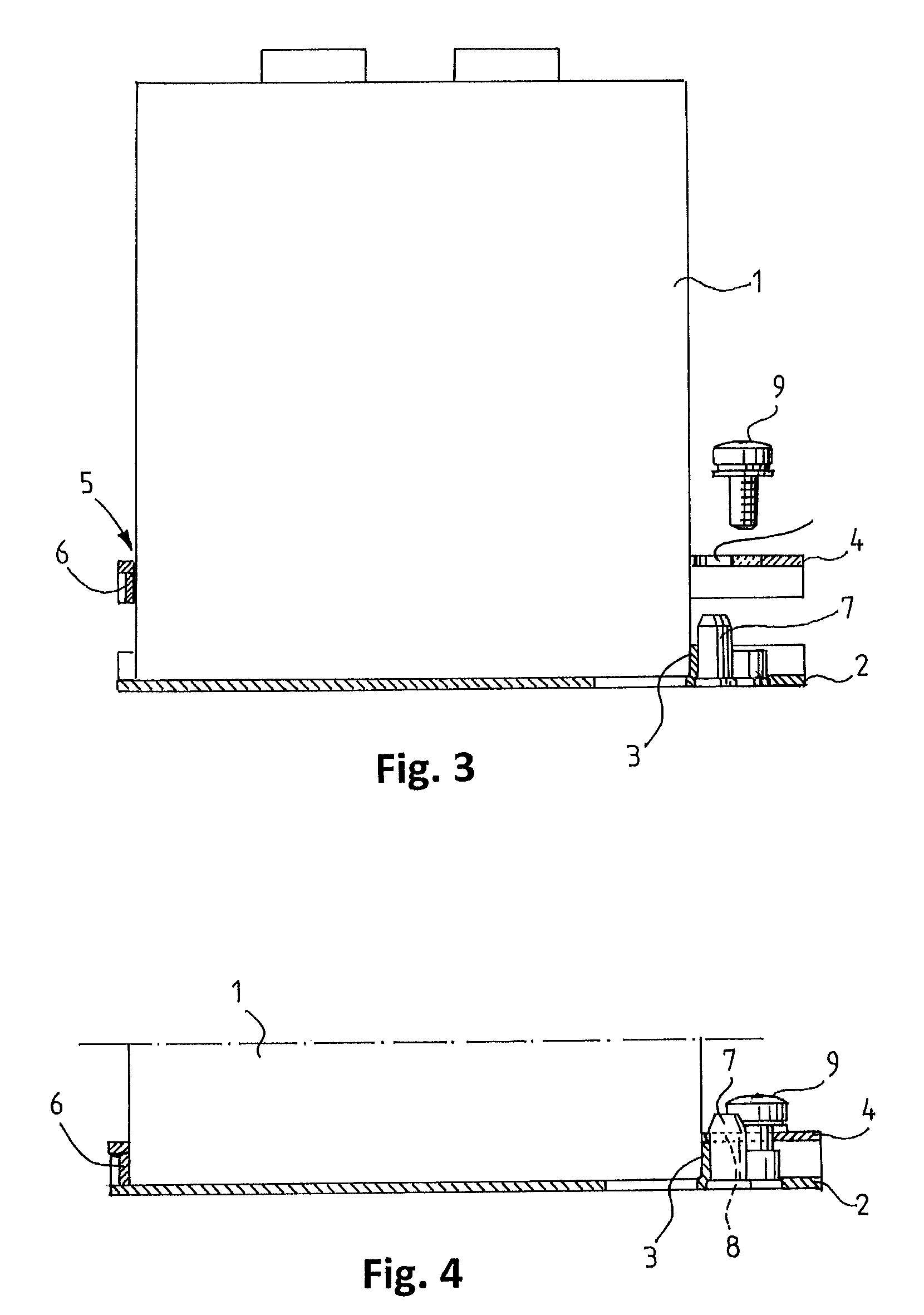
[0012]An exemplary embodiment of the disclosure can provide a new capacitor fastening wherein the wedge includes wedging pins provided in the panel and corresponding wedging holes provided in the tightening plate, the pins and holes, when in co-operation, being arranged to tighten the retainer of the panel and the edge of the tightening plate hole in opposite directions about the capacitor, perpendicular to an axial direction of the capacitor.

[0013]The disclosure is based on mounting the capacitor by two cross-tightening cellular plates. The plates tighten around the capacitor in a radial direction and, in addition, in a tightening step they wedge the capacitor tightly to the panel or the bottom plate.

[0014]The panel retainer can be formed of a curved collar corresponding to the shape of the outer surface of the capacitor rising from the panel, the collar extending on a pre-determined distance around the capacitor. Correspondingly, the hole in the tightening plate can be provided wi...


PUM


Abstract

A capacitor fastening for fastening a capacitor to a panel, whereby the capacitor, when mounted in place, is positioned in the panel, fastened at its lower part. The capacitor fastening includes a retainer in the panel at the mounting point of the capacitor for preventing lateral movement of the capacitor in at least one selected direction; a tightening plate arranged above the panel and to be fastened to the panel, which tightening plate has a hole substantially corresponding to the diameter of the capacitor above the mounting point of the panel; and a wedge between the panel and the tightening plate for tightening the retainer of the panel and the edge of the hole in the tightening plate from opposite directions against the capacitor.

Description

RELATED APPLICATION[0001]This application claims priority under 35 U.S.C. §119 to Finnish Patent Application No. 20116116 filed in Europe on Nov. 11, 2011, the entire content of which is hereby incorporated by reference in its entirety.FIELD[0002]The disclosure relates to capacitor fastening for fastening a capacitor to a panel, whereby the capacitor, when mounted in place, can be positioned in the panel and fastened there at its lower part. The capacitor fastening includes a retainer in the panel at the mounting point of the capacitor for preventing lateral movement of the capacitor in at least one selected direction, and a tightening plate arranged above the panel and to be fastened to the panel. The tightening plate has a hole substantially corresponding to the diameter of the capacitor above the mounting point of the panel. A wedge is provided between the panel and the tightening plate for tightening the capacitor in place between the panel and the plate.BACKGROUND INFORMATION[0...

Claims


Application Information

Patent Timeline
Patent Type & Authority Patents(United States)
IPC IPC(8): H02B1/01H01G2/04H01G4/28
CPCH01G2/04H01G4/28Y10T403/4628F16B2200/406H01R27/00
Inventor SEVAKIVI, PERTTIBJORKMAN, NIKO
Owner ABB (SCHWEIZ) AG
Why Eureka
Try Eureka