Terminal cover

a technology of terminal covers and covers, applied in the direction of electrical apparatus, connection, coupling device connection, etc., can solve the problems of not being able to improve workability, cover design, and affecting workability, and achieve the effect of improving workability

Inactive Publication Date: 2016-01-26
PANASONIC INTELLECTUAL PROPERTY MANAGEMENT CO LTD
View PDF19 Cites 4 Cited by
  • Summary
  • Abstract
  • Description
  • Claims
  • Application Information

AI Technical Summary

Benefits of technology

[0010]In view of the above, the present disclosure provides a terminal cover capable of improving the workability.
[0016]According to the present invention, the electric wires connected to the first screw terminals and drawn from the wire insertion holes pass through the wire insertion grooves existing between the second operation-purpose openings. Thus, the electric wires are hardly positioned above the second operation-purpose openings. Accordingly, the electric wires are hard to become obstacles when operating the screw terminals. This helps improve the workability.

Problems solved by technology

In this case, when electric wires 42 are attached or detached by operating the second screw terminals 32, the electric wires 41 connected to the first screw terminals 31 become obstacles, thereby impairing the workability.
The conventional terminal cover is not designed to solve the aforementioned problem and is not capable of improving the workability.

Method used


Image

  • Terminal cover
  • Terminal cover
  • Terminal cover

Examples


Embodiment Construction

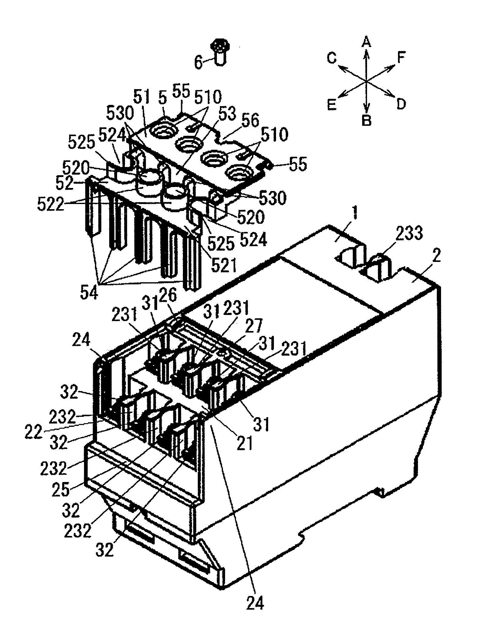
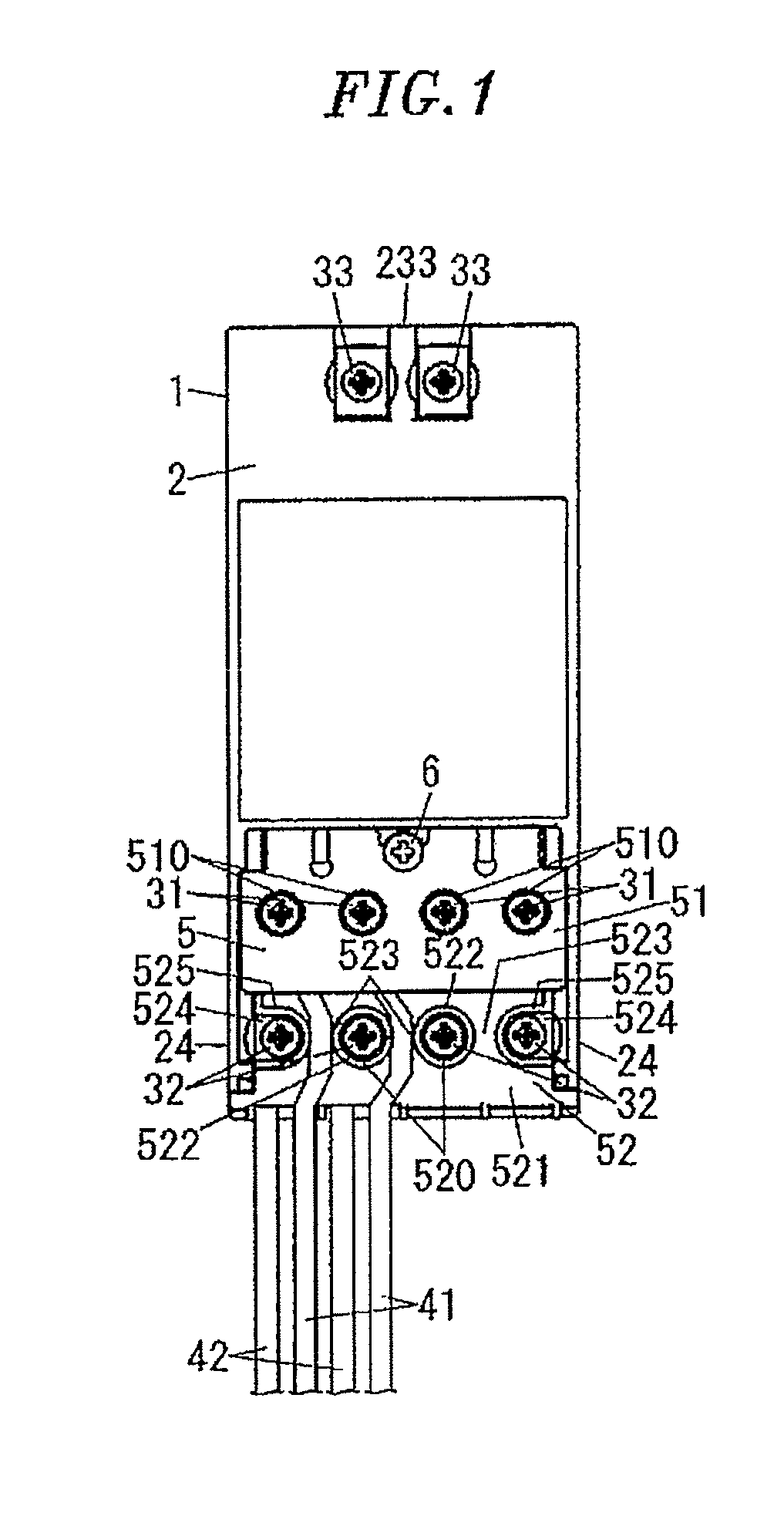
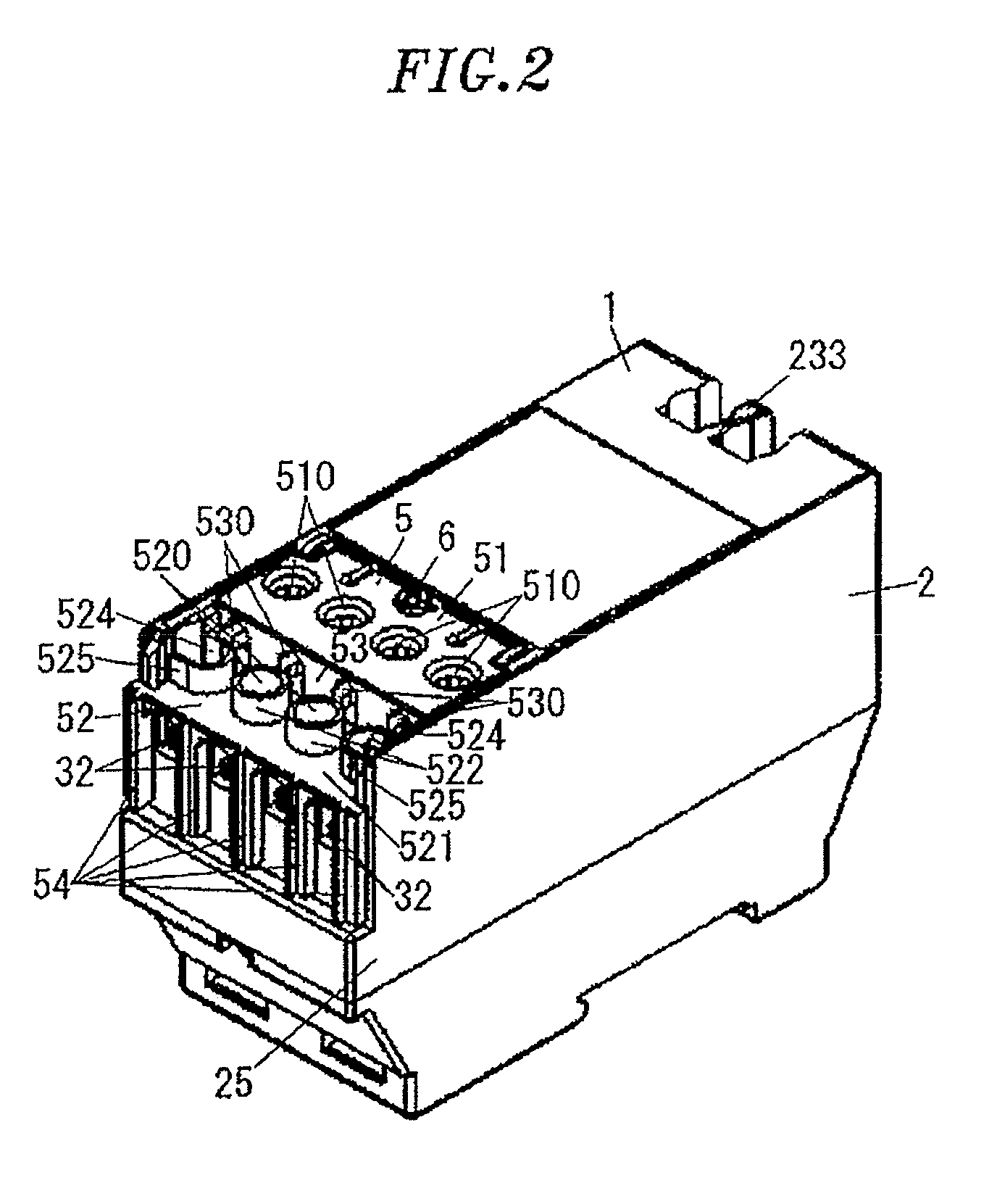
[0028]The present invention is directed to a terminal cover 5 attached to a terminal device (relay 1) which is fixed to a fixing target with the lower surface thereof facing toward the fixing target. The terminal device (relay 1) includes a housing 2 having a stepped portion including an upper step 21 and a lower step 22 which extends along an end of an upper surface of the terminal device. The lower step 22 is closer to the end than the upper step 21. The terminal device (relay 1) further includes a plurality of first screw terminals 31 installed in the upper step 21 of the stepped portion and arranged side by side along the upper step 21 and a plurality of second screw terminals 32 installed in the lower step 22 and arranged side by side along the lower step 22. The terminal cover 5 includes a first cover portion 51 positioned above the first screw terminals 31, a second cover portion 52 positioned above the second screw terminals 32, and a connecting portion 53 disposed between t...


PUM


Abstract

A terminal cover is capable of improving the workability. The terminal device includes a first cover portion to be positioned above the first screw terminals, wherein the first cover portion including the first operation openings which respectively expose screws of the first screw terminals, a second cover portion to be positioned above the second screw terminals, the second cover portion including the second operation openings which respectively expose screws of the second screw terminals. And the terminal device further includes a connecting portion connecting the first cover portion with the second cover portion and including wire insertion holes through which electric wires connected to the first screw terminals respectively pass and wire insertion paths which communicate with the wire insertion holes and through which the electric wires respectively pass, each insertion path being provided on an upper surface of the second cover portion between two adjacent second operation openings.

Description

CROSS-REFERENCE TO RELATED APPLICATIONS[0001]This application claims priority to Japanese Patent Application No. 2013-233300 filed on Nov. 11, 2013, the entire contents of which are incorporated herein by reference.TECHNICAL FIELD[0002]The present invention disclosure to a terminal cover and, more particularly, to a terminal cover which is attached to a terminal device having screw terminals arranged in upper and lower steps of a stepped portion.BACKGROUND ART[0003]In the related art, there is provided a terminal cover which is attached to a terminal device having screw terminals arranged in upper and lower steps of a stepped portion (see, e.g., Japanese Patent Application Publication No. S62-195863).[0004]A terminal device will be described in detail by taking a relay 1 shown in FIGS. 8 to 10 as an example. The relay 1 includes a housing 2 which is fixed such that one surface (hereinafter referred to as “lower surface”) of the housing 2 faces toward a fixing target (not shown) such...

Claims


Application Information

Patent Timeline
Patent Type & Authority Patents(United States)
IPC IPC(8): H01R9/22H01R13/447H01R9/24
CPCH01R13/447H01R9/2475
Inventor SASAKI, TOMOAKISUMINO, YASUHIRO
Owner PANASONIC INTELLECTUAL PROPERTY MANAGEMENT CO LTD
Why Eureka
Try Eureka