Flush fitting pipe lining system

a technology of pipe lining and flush fitting, which is applied in the direction of screw threaded joints, drilling pipes, mechanical equipment, etc., can solve the problems of ineffective time and cost, ineffective pipe lining, and ineffective pipe lining, so as to prevent the strand of liner from dislodging and maximize the inner diameter of the lined pipe

Active Publication Date: 2016-02-09
DLT ACQUISITION
View PDF19 Cites 0 Cited by
  • Summary
  • Abstract
  • Description
  • Claims
  • Application Information

AI Technical Summary

Benefits of technology

[0011]Accordingly, an object of the present invention is to provide a standardized or universal internal liner coupling assembly that can accommodate the wide variety of pipe end constructions currently in use without the need for special modifications to proprietary pipe end threads and couplings. In addition, a further object of the present invention is to provide a liner coupling assembly that maximizes the inner diameter of the lined pipe while also preventing strands of liner from dislodging along the inner diameter of the liner.

Problems solved by technology

An obstacle with insertion of such an assembly is that the threaded pipes or couplings need to be machined and threaded with special provisions to accommodate the lining process.
This proves to be ineffective in time and cost as well as productivity.
Additionally, it has been discovered that such liner systems decrease the inner diameter of pipe and prevent tooling from easily traveling through the well bore.
Still further, conventional liner systems also fail to adequately protect the liner face.
This leads to liner strands being dislodged along the inner diameter of the liner, thereby negatively effecting product performance reliance.

Method used


Image

  • Flush fitting pipe lining system
  • Flush fitting pipe lining system
  • Flush fitting pipe lining system

Examples


Embodiment Construction

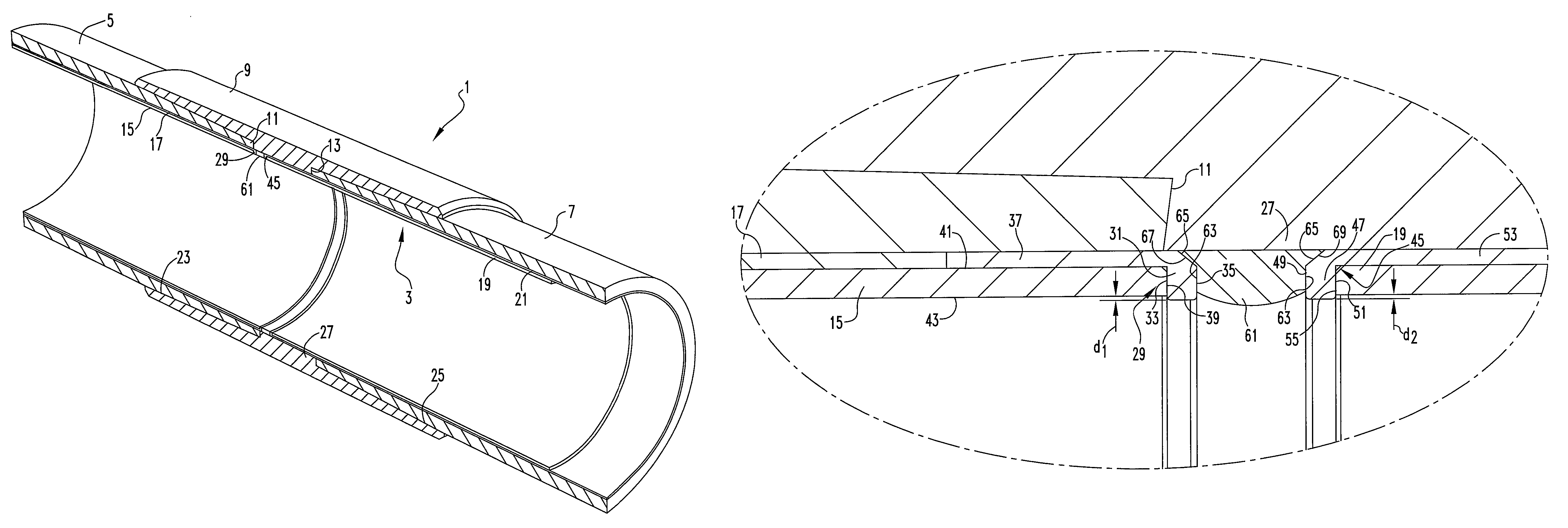
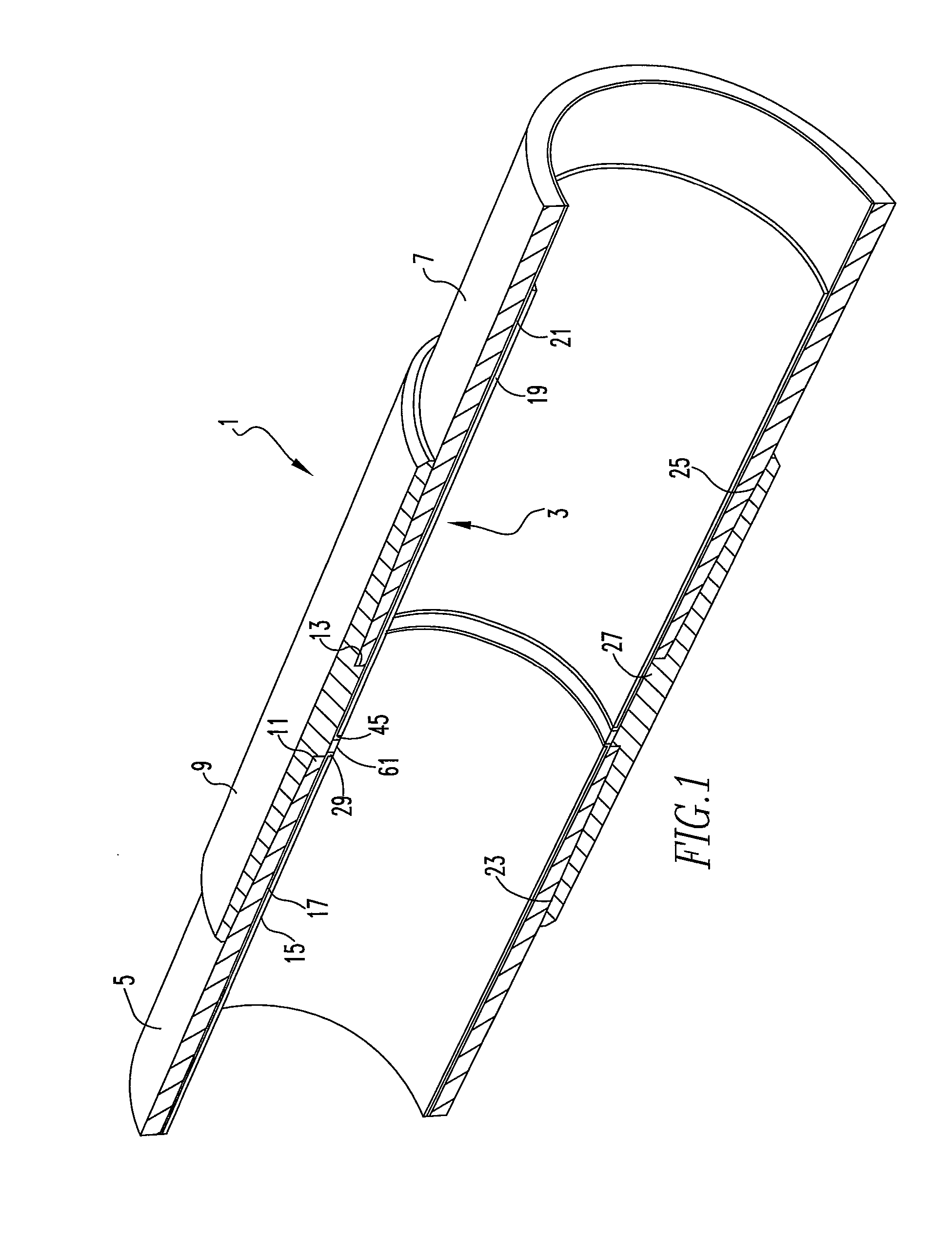
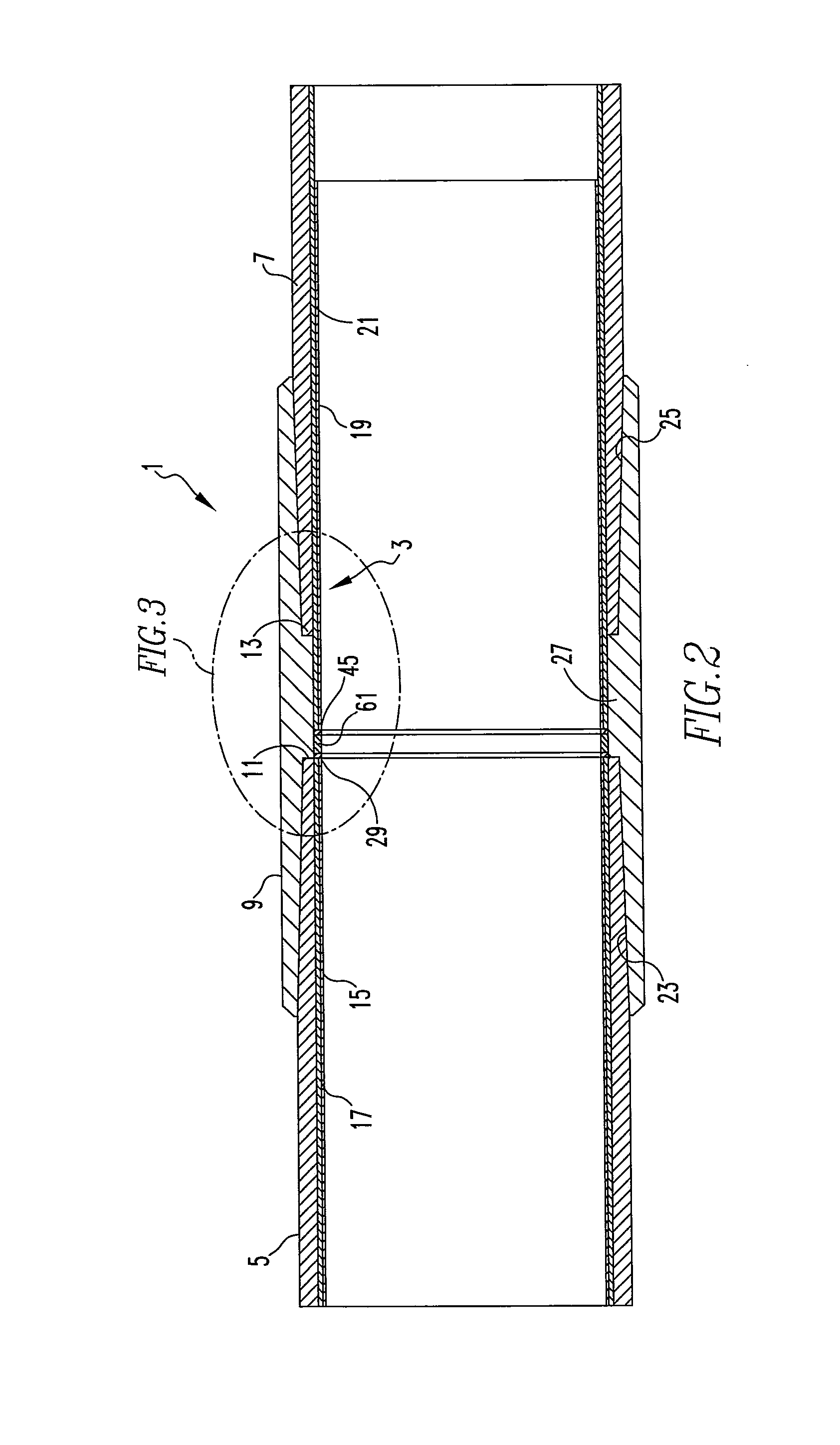
[0021]For purposes of the description hereinafter, the terms “upper”, “lower”, “right”, “left”, “vertical”, “horizontal”, “top”, “bottom”, “lateral”, “longitudinal” and derivatives thereof shall relate to the invention as it is oriented in the drawing figures. However, it is to be understood that the invention may assume various alternative variations, except where expressly specified to the contrary. It is also to be understood that the specific devices illustrated in the attached drawings, and described in the following specification, are simply exemplary embodiments of the invention.

[0022]A conventional process of connecting pipes in the oil and gas industry utilizes steel threaded couplings, which are machined and threaded and adapted to accommodate an insert liner. The present invention relates generally to a coupling assembly, denoted generally as reference numeral 1, used to connect adjacent or opposing pipe segments, and a liner assembly, denoted generally as reference numer...


PUM

PropertyMeasurementUnit
distanceaaaaaaaaaa
45° angleaaaaaaaaaa
distance d1aaaaaaaaaa

Abstract

A liner assembly includes a first ring member, a second ring member, a corrosion barrier ring, a first liner, and a second liner. The first ring member includes a body member having a first end and a second end. The first end has a flange extending substantially perpendicularly therefrom. The second ring member includes a body member having a first end and a second end. The second end has a flange extending substantially perpendicularly therefrom. The body member of the first ring member extends along a face of the first liner a first distance beyond an inner diameter of the first liner. The body member of the second ring member extends along a face of the second liner a second distance beyond an inner diameter of the second liner.

Description

BACKGROUND OF THE INVENTION[0001]1. Field of the Invention[0002]The present invention relates to a coupling system utilized in connecting end-to-end lined pipe used in oil wells and the like, and, more particularly, to a lining system for use in a joint between two pipe segments and a method of connecting two unmodified pipe segments with a lining system which will prevent corrosion and maximize the inner diameter of the bore.[0003]2. Description of Related Art[0004]Many downhole oil-production operations are carried out in highly corrosive environments resulting from production and / or re-injection of hydrocarbons and formation of brinewaters containing salts and gases, such as hydrogen sulfide and carbon dioxide which can pass through the pipe interior.[0005]To provide a useful life to the lengths of steel pipes that are used in such environments, corrosive resistant liners are installed within each pipe length before it is installed into the downhole string. Appropriate threaded c...

Claims


Application Information

Patent Timeline
Patent Type & Authority Patents(United States)
IPC IPC(8): F16L58/02F16L58/10F16L15/00F16L58/18E21B17/08
CPCE21B17/08F16L15/001F16L58/1036F16L58/182
Inventor ZAPATA, OSCARBREMNER, MARTIN
Owner DLT ACQUISITION
Why Eureka
Try Eureka