Self-extending electrical hose

a technology of electrical hoses and hoses, which is applied in the direction of insulated conductors, cables, conductors, etc., can solve the problems of cumbersome handling and transportation of hoses attached to vacuum canister units or to other bodies supporting vacuum motors, and affecting the overall efficiency of cleaning operation. , to achieve the effect of reducing the overall efficiency of cleaning operation, and reducing the overall efficiency

Inactive Publication Date: 2010-06-15
FLEXIBLE TECH INC
View PDF12 Cites 50 Cited by
  • Summary
  • Abstract
  • Description
  • Claims
  • Application Information

AI Technical Summary

Benefits of technology

[0012]The construction of the hose disclosed herein is capable of neat retraction into the outer constraining hose, while incorporating multiple conducting wires to supply the electrical demands at the user end of the self-extending hose. This construction comprises a wire reinforcing member, preferably a steel wire, which is wound through a series of turns to preferably produce a helical shape not unlike that of a compression spring. The turns of the reinforcing member, as well as the interstitial space between the turns, receives a series of plies of thermoplastic material to create a flexible cover. The plies are formed so as to have an outward fold between the turns while the self-extending hose is in the unrestrained condition. The outward folding maximizes the inner diameter of the hose for a given construction, and accommodates the retraction of the self-extending hose.
[0016]It is another object of this invention to provide a construction for a hose that is light weight.

Problems solved by technology

However, a substantial length of hose attached to a vacuum canister unit, or to another body which supports a vacuum motor, becomes cumbersome to handle and transport after vacuum operations have been completed.
Moreover, during such operations when a portable vacuum unit merely needs to be relocated to another area requiring its use, the length of hose may be unwieldy and difficult to handle because of its bulk, and may hamper or degrade the overall efficiency of the cleaning operation.
Kanao suggests that its construction provides extension / contraction zones that can be extended in the direction of the hose axis by manually pulling the hose, and that its use will result in “little user fatigue.” Thus, the hose is not actually capable of self-extension.

Method used


Image

  • Self-extending electrical hose
  • Self-extending electrical hose
  • Self-extending electrical hose

Examples


Embodiment Construction

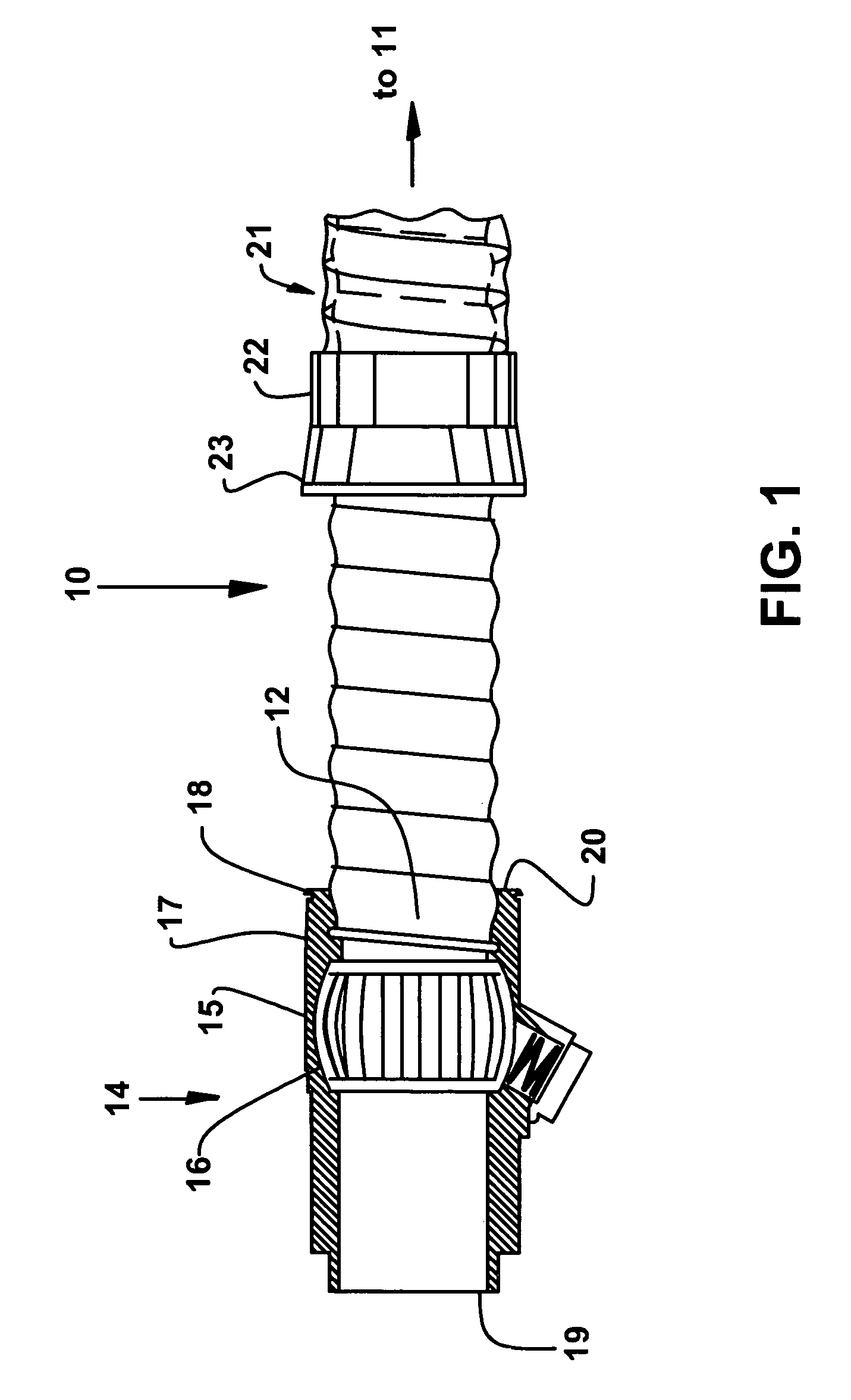
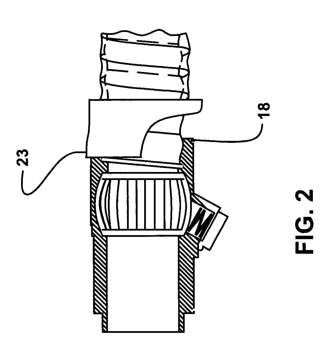
[0031]A section of a self-extending hose 10 according to the invention is shown in FIG. 1 as it is incorporated into a vacuum system. The particular vacuum system of FIG. 1 in which the hose 10 is incorporated does not in any way limit usage of the hose of this invention, and is merely meant to provide one example of its possible use.

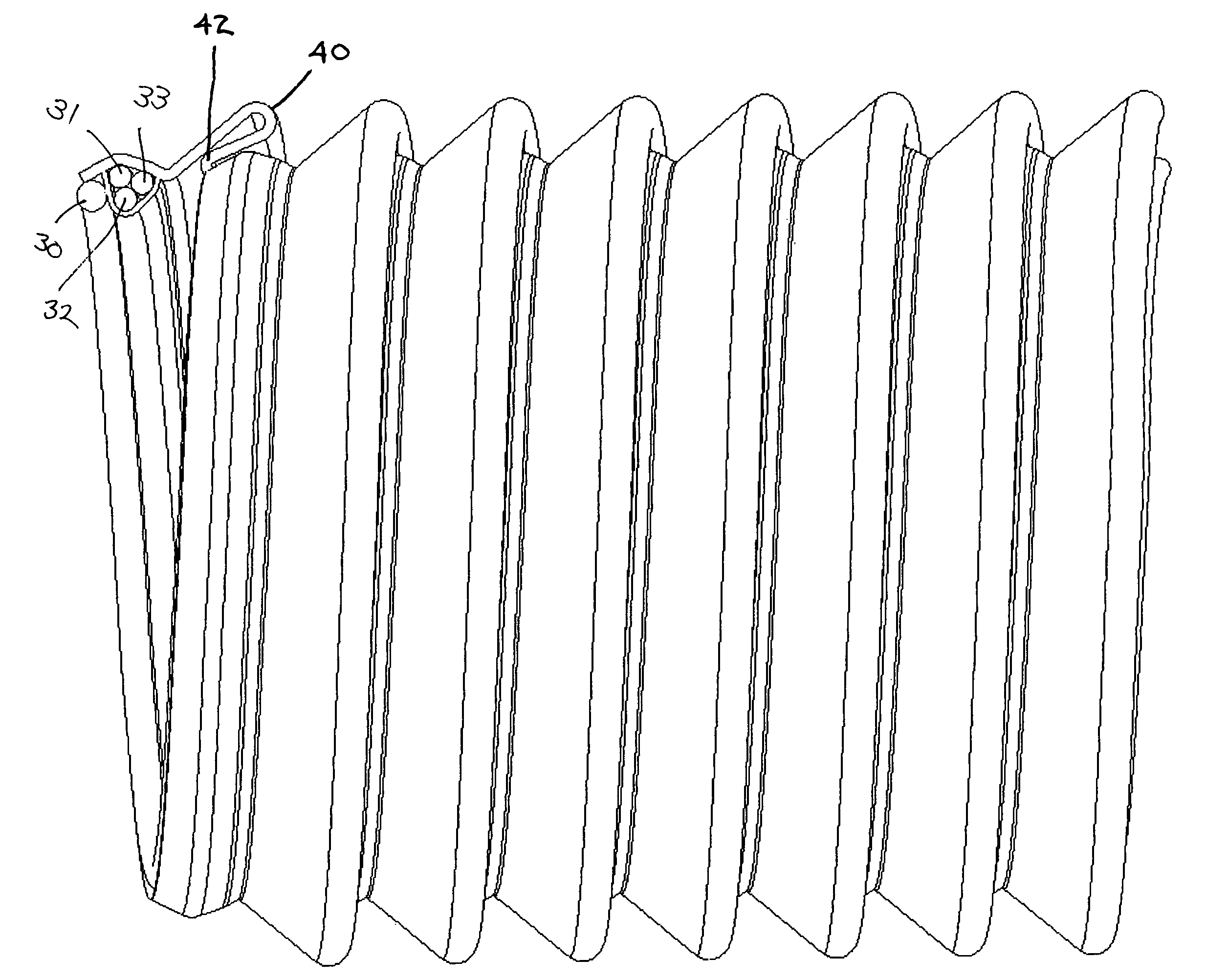
[0032]In the vacuum system of FIG. 1, a first end 11 of the self extending hose 10 is connected to a source of negative pressure (not shown), while the other end is connected to a nozzle assembly 14. The self-extending hose 10 is generally surrounded, in this exemplary embodiment, by a constraining hose 21, which has a slightly larger diameter. The constraining hose 21 terminates in a cuff 22 that has a flared end 23. The self-extending hose 10 may normally extend a substantial distance beyond the cuff 22 of constraining hose 21. The constraining hose 21 may generally be flexible, but is preferably not a stretch hose.

[0033]The nozzle assembly 14 may hav...


PUM


Abstract

A hose construction adapted for efficiently conveying fluids while extended, but capable of neatly contracting to a fraction of its extended length for storage or transportation, while integrally incorporating lines for electrical requirements. Storage may be within an outer hose and may be triggered via closure of a valve within a nozzle so that negative pressure causes contraction of the folds of the hose. The contracted hose has a length that is a fraction of its normal extended length. The hose construction incorporates a wire reinforcing member which may bias the hose for self-extension and may also function as part of the electrical system. The electrical lines may comprise stranded copper wires to conduct power and / or serve as a remote activation circuit. The hose configuration may have a cover with external folds, which maximizes flow and provides a cushioning outer diameter to prevent damage to the hose.

Description

FIELD OF THE INVENTION[0001]This invention relates generally to flexible hose construction, and more particularly to a multi-wire electrical stretch hose construction capable of self-extension upon removal of negative pressures.BACKGROUND OF THE INVENTION[0002]Flexible hoses have been utilized in many different applications involving transporting gases, liquids, and even solids, which are often in the form of particulate matter. Although most hose applications involve pumping material under pressure from a first location to second location, flexible hoses are frequently utilized in conjunction with electrical motors that create suction or negative pressure to create a vacuum.[0003]Vacuum hoses have numerous applications, such as the intake vacuum to supply air into the manifold of a combustion engine, the pump and filter of a swimming pool's water cleaning system, industrial uses for materials processing or manufacturing as in the production of composite parts that are vacuum bagged...

Claims


Application Information

Patent Timeline
Patent Type & Authority Patents(United States)
IPC IPC(8): F16L11/00F16L11/12
CPCF16L11/16F16L11/1185
Inventor SMITH, STACYCAMPBELL, KEN
Owner FLEXIBLE TECH INC
Why Eureka
Try Eureka