Removable anchoring device usable as a suspension bolt

a technology of suspension bolts and anchoring devices, which is applied in the field of retractable anchoring devices, can solve the problems of not being able to be removed after use, being placed by means of fastening tools, and being difficult to use in the field of rock climbing, load hoisting, etc., and achieves the effect of simplifying design

Active Publication Date: 2016-02-09
ZEDEL CORP
View PDF8 Cites 15 Cited by
  • Summary
  • Abstract
  • Description
  • Claims
  • Application Information

AI Technical Summary

Benefits of technology

[0016]The stop part determines a minimum insertion length enabling a particularly dependable fixing of the device in the wall. In addition, such an arrangement, after insertion of the device in the hole drilled in the wall, enables a sufficient distance to be maintained between the wall and the stop of the female body so that the latter can be used as a hand hold for handling the female body on the shank. Furthermore, the elastic compression part ensures instantaneous locking of the device in the hole drilled in the wall. This device presents the advantage of being able to be fitted and removed quickly with only one hand.
[0045]According to another feature of the invention, the stop part is provided with load suspension means. The load is thus applied as close as possible to the wall, which reduces the flexural stresses undergone by the part of the male body outside the hole.

Problems solved by technology

Certain of these devices present the drawback of being usable once only and of not being able to be removed after use.
Furthermore, they can only be placed by means of fastening tools and are therefore difficult to use in the field of rock-climbing, load hoisting or whenever a wall has to be left devoid of any device.

Method used


Image

  • Removable anchoring device usable as a suspension bolt
  • Removable anchoring device usable as a suspension bolt
  • Removable anchoring device usable as a suspension bolt

Examples


Embodiment Construction

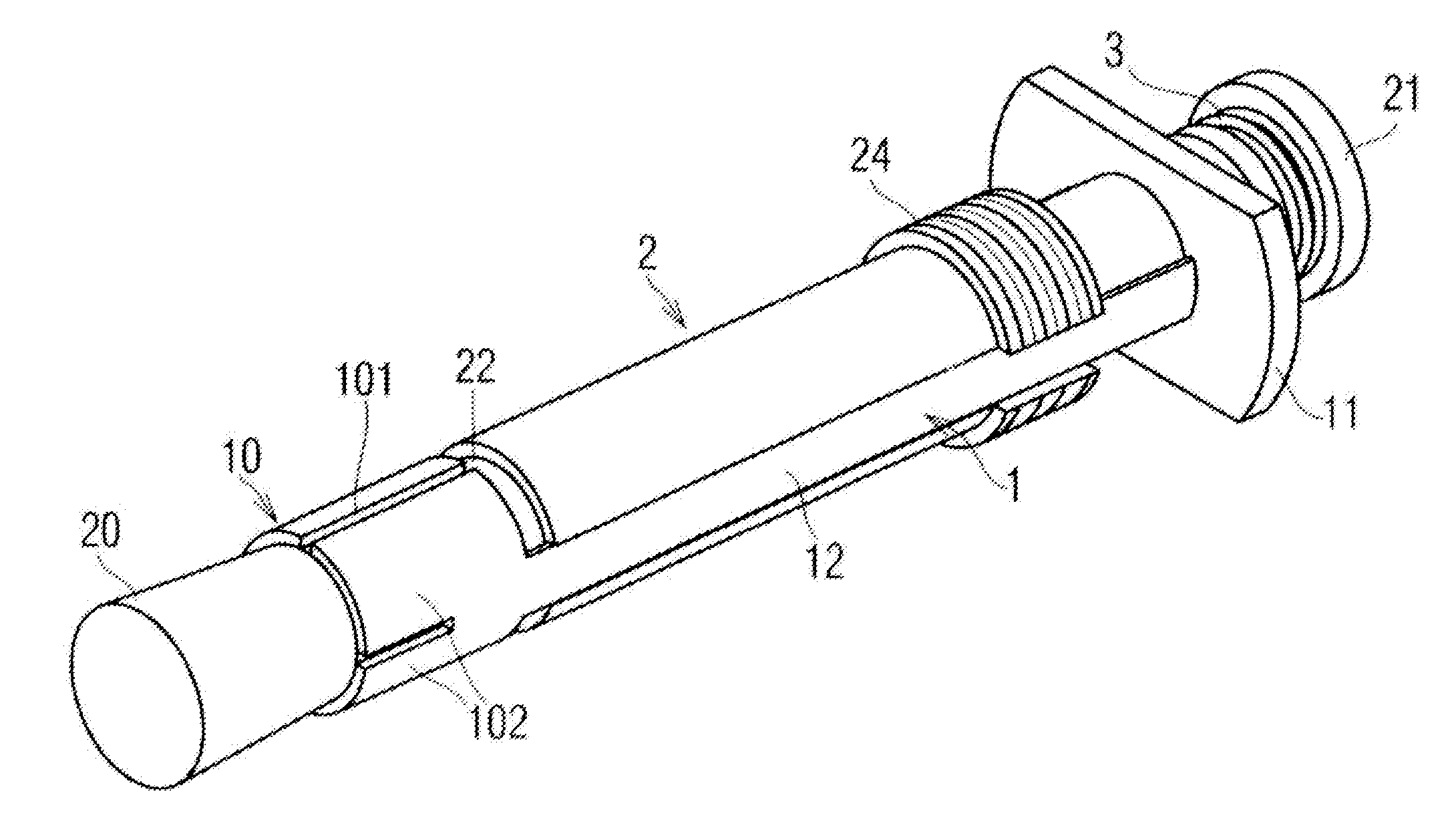
[0059]As represented, the removable anchoring device according to the invention, of the bolt for rock-climbing type, is designed to be engaged in removable manner in a hole F drilled beforehand in a wall P in order to be embedded therein. This anchoring device is designed to support a mechanical load. This mechanical load is mainly applied on the anchoring device in radial manner and generates flexural stresses.

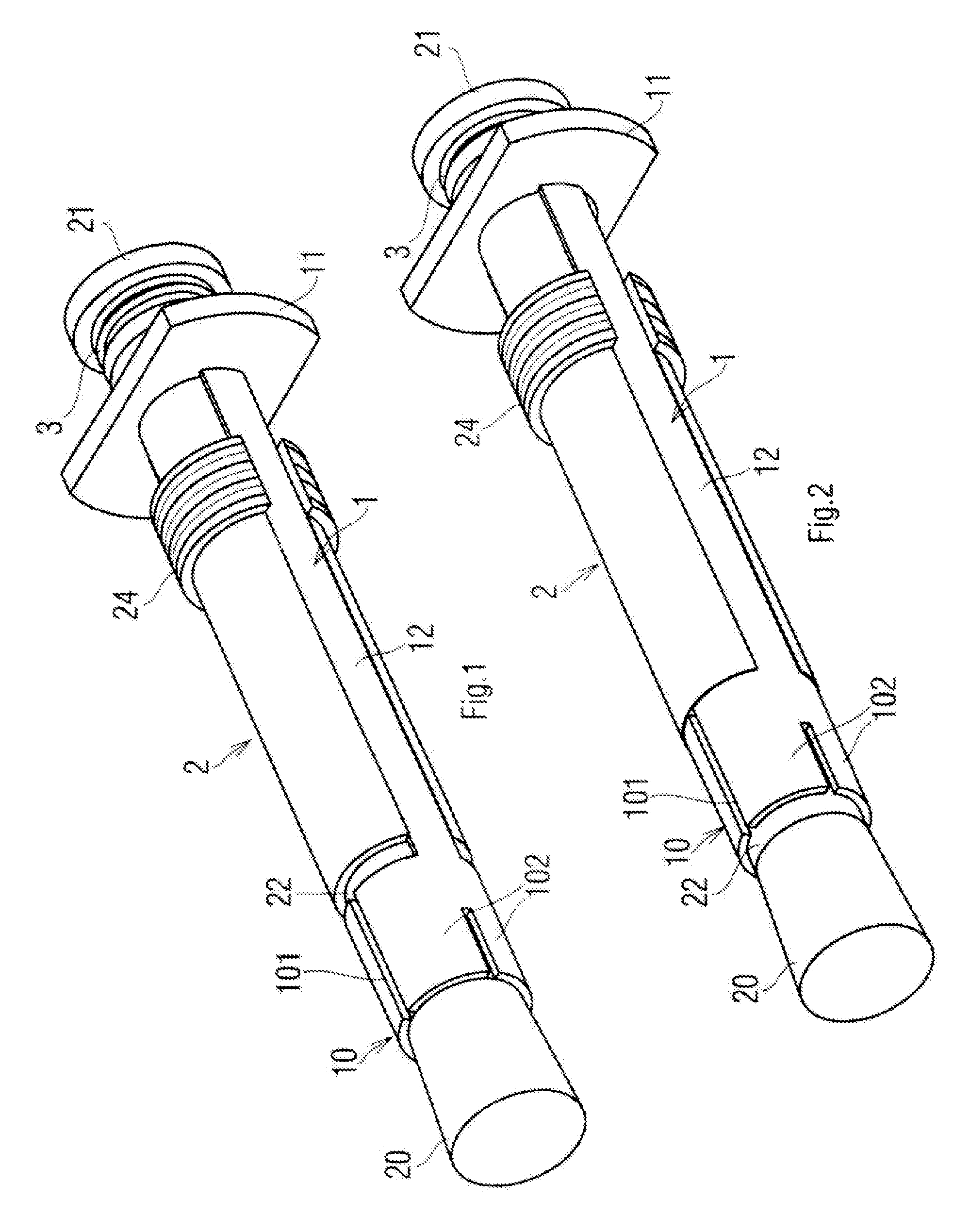
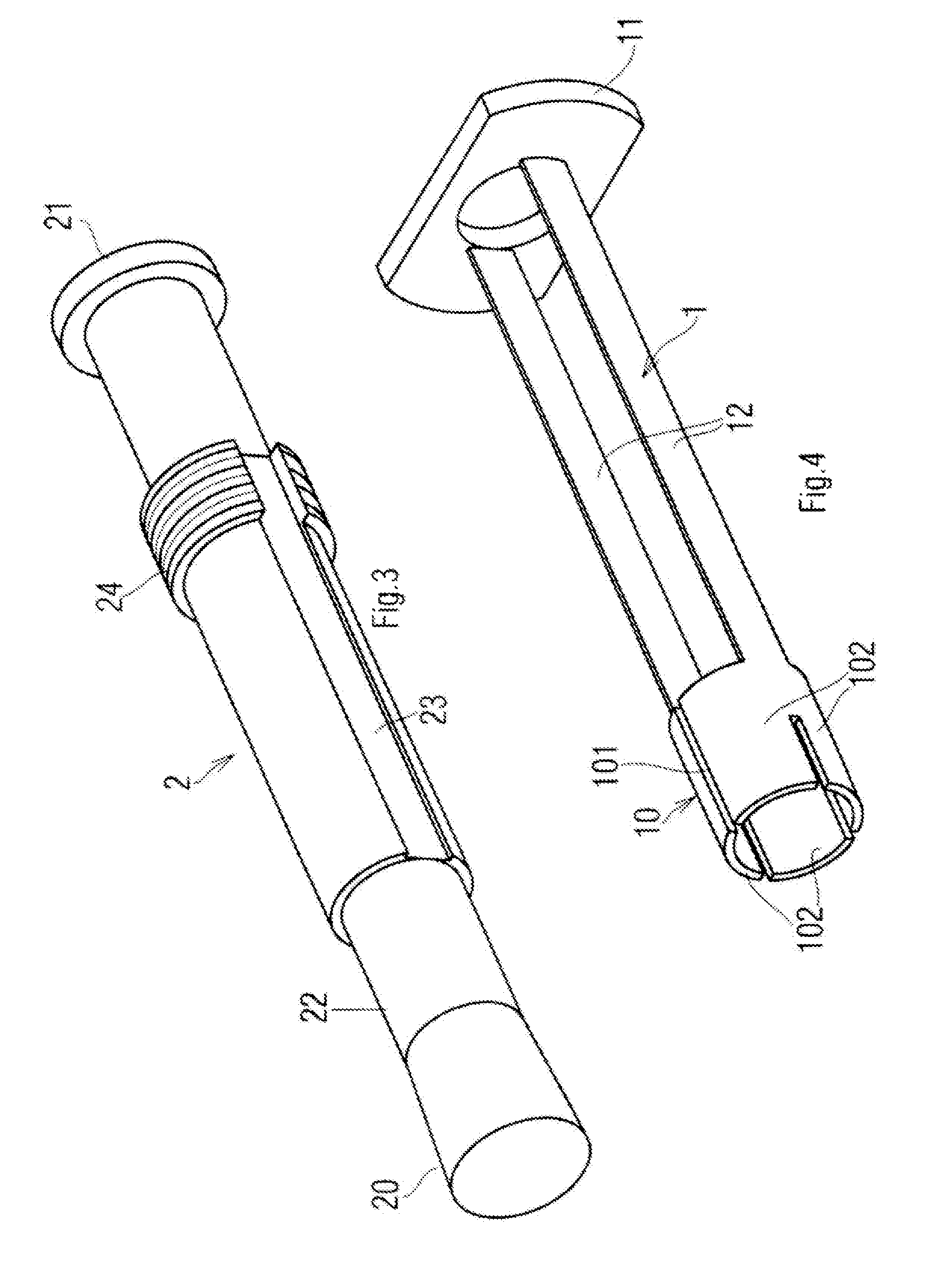
[0060]The anchoring device according to the invention comprises on the one hand a female body 1 provided with a flexible, radially expandable front area 10, and on the other hand a male body 2, substantially in the form of a cylindrical shank, slidingly engaged in female body 1.

[0061]With reference to FIGS. 1 and 2, this male body 2 comprises at its front end an expansion head 20 biased towards and into the expandable area 10 of female body 1 by a flexible part 3 engaged on male body 2 and fitted in compression between a rear stop 11 of female body 1 and a rear stop 21 of mal...


PUM


Abstract

A removable anchoring device designed to be inserted in a hole drilled in a wall, and designed to support a mechanical load, including a female body provided with a radially expandable front area designed to be inserted in the hole and with a rear stop designed to be outside the hole, a male body slidingly engaged in the female body including an expansion head at its front end, the male body including a rear stop designed to be outside the hole, a flexible compression part fitted in compression between the stop of the female body and the stop of the male body in order to bias the male body and the female body in the direction of engagement of the expansion head in the radially expandable area, the male body presenting a stop part determining a penetration length into the drilled hole.

Description

GENERAL TECHNICAL BACKGROUND AND PRIOR ART[0001]The present invention relates to the field of equipment used both for rock-climbing and for suspending or fixing objects to a rock or concrete or other wall and relates more particularly to a removable anchoring bolt. The invention also relates to the field of hoisting heavy loads (girders, concrete blocks, etc.).[0002]Anchoring devices designed to be anchored in holes drilled in solid materials constituted by rock or concrete are known from the state of the art. Certain of these devices present the drawback of being usable once only and of not being able to be removed after use. Furthermore, they can only be placed by means of fastening tools and are therefore difficult to use in the field of rock-climbing, load hoisting or whenever a wall has to be left devoid of any device.[0003]Removable anchoring devices, of bolt type, able to be used to suspend objects on walls are also known from the state of the art. The advantage of such devic...

Claims


Application Information

Patent Timeline
Patent Type & Authority Patents(United States)
IPC IPC(8): A47G29/02F16M13/02F16B13/06F16B13/00A63B29/02
CPCF16B13/00A63B29/02A63B29/024F16B13/065F16M13/022F16B2013/009
Inventor CABRIT, ERICCLUZON, PAUL
Owner ZEDEL CORP
Why Eureka
Try Eureka