System and method for fluid cooling of electronic devices installed in a sealed enclosure

a technology for electronic devices and sealed enclosures, applied in cooling/ventilation/heating modifications, instruments, computing, etc., can solve the problems of significant thermal energy generation of electronic devices during operation, high construction and operational costs, and significant reduction of the functional life of electronic devices

Active Publication Date: 2016-02-09
SMITH DAVID LANE
View PDF63 Cites 21 Cited by
  • Summary
  • Abstract
  • Description
  • Claims
  • Application Information

AI Technical Summary

Benefits of technology

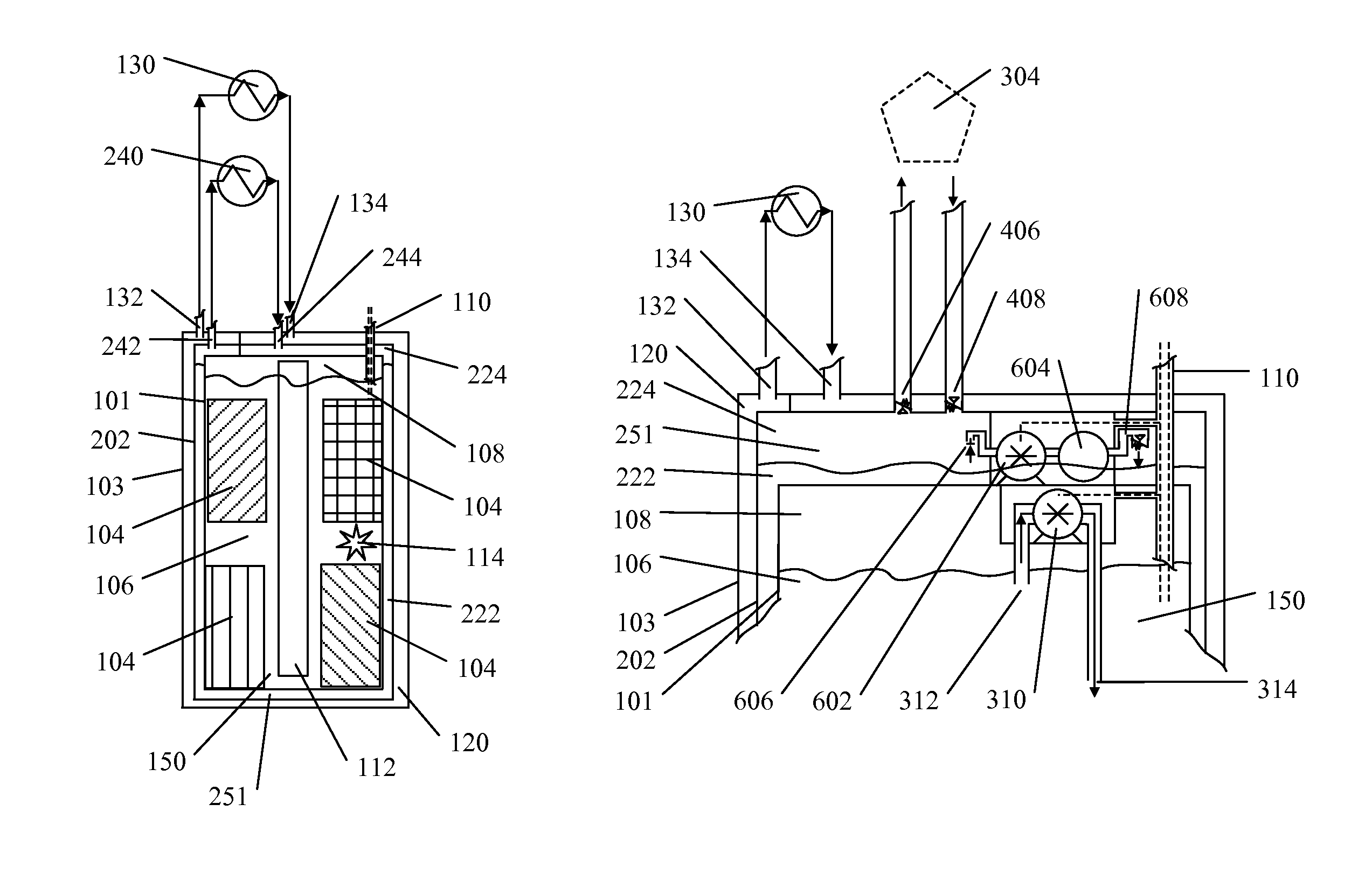
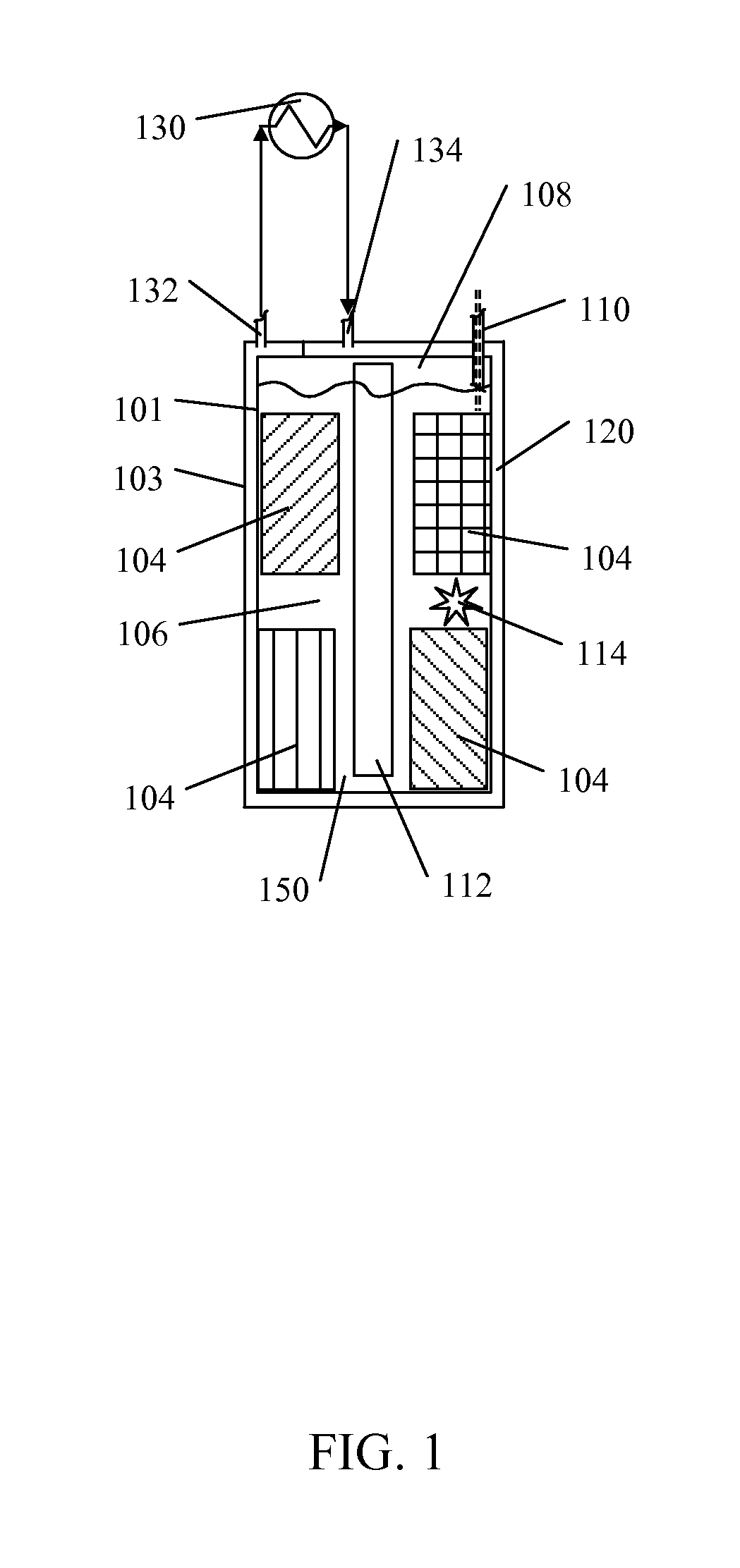
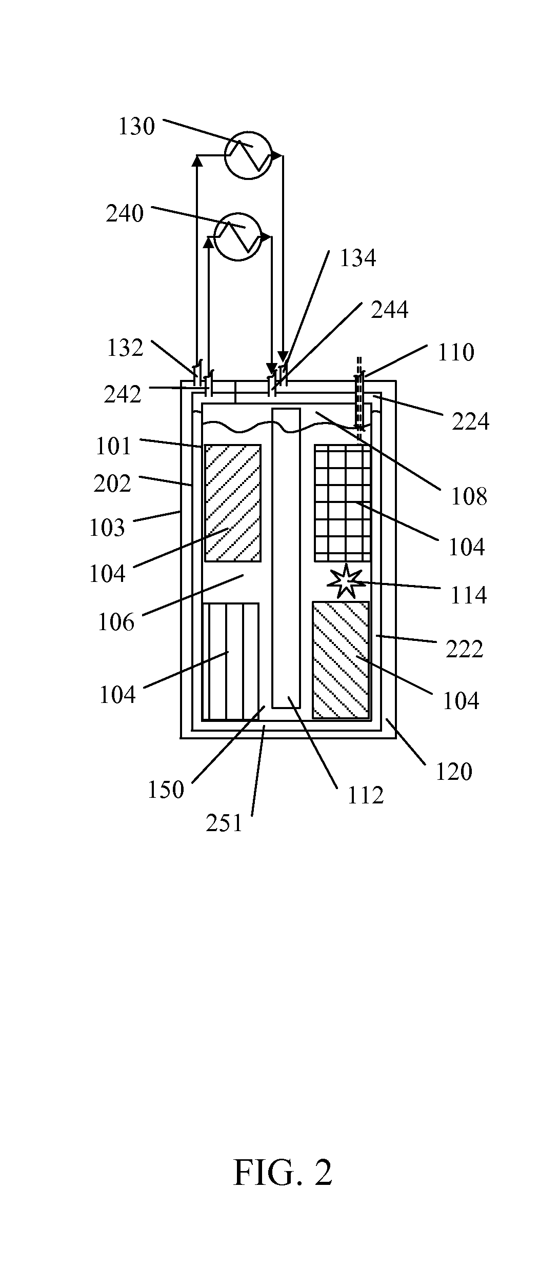
[0013]At least one embodiment described herein provides a cooling system for electronic devices installed in a sealed enclosure. Such embodiments are optimized for effective and efficient direct and indirect transfer of thermal energy away from heat-generating electronics into the surrounding environment. Designs embody enclosing structures comprised of walls that enclose an interior sealed space containing heat generating components and a dielectric thermally conductive fluid (“primary dielectric thermally conductive fluid”). Such walls are comprised of inner, outer, and optional intermediate walls such that additional and distinct thermally conductive fluids (“secondary thermally conductive fluids”) are circulated within the enclosure walls to an external local or remote heat exchange loop. The sealed enclosure may be located in a variety of environments comprising limited to, raised or slab floor datacenters, commercial buildings, residential buildings, outdoor locations, subsurface structures, and direct subsurface installation. The design leads to significant reductions in capital, infrastructure, power, cooling, maintenance, and operational costs associated with deploying computing hardware. In addition, the design provides for a high degree of physical, electrical, and magnetic security for the enclosed electronics.
[0015]Electronic devices may be disposed within the interior of the sealed enclosure in a variety of configurations to facilitate thermal transfer and best practice process efficiency. The enclosed electronic devices dissipate internally generated heat into the innermost volume, the primary dielectric thermally conductive fluid, and the innermost thermally conductive walls of the sealed enclosure. Heat is transported from the innermost surface of the walls of the sealed enclosure to one or more secondary thermally conductive fluids within the walls of the enclosure. The walls of the enclosure may be thermally connected by mechanical connection or other means. Cooling fins may be affixed to any wall surfaces to aid in heat transport and dissipation.
[0020]To enhance the security of the electronic devices in the sealed enclosure, a functional “poison pill” system may be implemented to provide an electrical, magnetic, chemical, and / or mechanical means of rendering the electronic devices and any content stored on those devices to be permanently unusable and unreadable.

Problems solved by technology

Electronic devices generate significant amounts of thermal energy during operation.
The functional lifetime of electronic devices is significantly diminished by excess heat buildup.
Although this process is effective, it is complex process with a number of systems that must be constantly maintained to produce the desired environment thus having high construction and operational costs.
Air based cooling faces significant risks from a) internal fan and cooling failures, b) server room cooling failures and inconsistencies, c) fire control systems, d) unauthorized human access, e) maintenance failures and mistakes, and f) natural disasters.
Taken together, these factors typically require specialized and costly installation space for electronic devices such as computer servers.
Further, air-based cooling of electronic systems can double the total amount of electrical energy required to operate these systems, resulting in a costly and wasteful means of operating such systems.
However, these processes have not seen widespread adoption for one or more possible reasons.
Component level liquid cooling designs tend to introduce significant complexity to operations and maintenance while increasing server room risks to coolant leaks and failures.
System level liquid cooling designs reduce the overall number of cooling interconnects, but have similar problems.
To further complicate the liquid cooling server room installations, liquid cooled systems require new server room procedures, operations, and training and expose owner and operators to additional liabilities from liquid damage.
And notably, production electronic devices and servers are rarely available in liquid cooling configurations.
Succinctly, the cost savings associated with current liquid cooling designs are overshadowed by the increased costs of purchasing, constructing, and operating liquid cooled servers and solutions.
Individual electronic devices and servers may fail over time, but the virtualized nature of software based compute and storage units mean that an individual failures only slightly decreases the overall capability of a collection of servers but in no way compromises the data processing, storage, and communication functions as a whole.
No. 2015 / 0000319 (January 2015) are challenging the assumptions and designs of data centers and server rooms.

Method used


Image

  • System and method for fluid cooling of electronic devices installed in a sealed enclosure
  • System and method for fluid cooling of electronic devices installed in a sealed enclosure
  • System and method for fluid cooling of electronic devices installed in a sealed enclosure

Examples


Embodiment Construction

[0031]Although described with reference to certain embodiments, those with skill in the art will recognize that the disclosed embodiments have relevance to a wide variety of areas in addition to those specific examples described below. Further, elements from one or more embodiments may be used in other embodiments and elements may be removed from an embodiment and remain within the scope of this disclosure.

[0032]All references, including publications, patent applications, and patents, cited herein are hereby incorporated by reference to the same extent as if each reference were individually and specifically indicated to be incorporated by reference and were set forth in its entirety herein; provided, however, to the extent there exists a conflict between this disclosure and a document incorporated by reference, this disclosure shall control.

[0033]As referenced herein, the terms “sealed enclosure” and “containment vessel” are used interchangeably.

[0034]As referenced herein, the terms...


PUM


Abstract

A system and method for cooling electronic devices disposed with the innermost volume of a hollow-walled fluid-tight sealed enclosure. Thermally conductive fluids that fill one or more volumes within the hollow walls of said sealed enclosure may be circulated away from said sealed enclosure to an external heat exchange mechanism. The innermost volume of the sealed container contains one or more single phase or multi-phase dielectric thermally conductive fluids, which may be circulated passively by convection or actively by means of a pump, bubbler, fan, propeller or other means. Pressure balancing mechanisms may be included to maintain suitable pressure of gaseous fluid in the innermost volume of the sealed container.

Description

RELATED APPLICATION[0001]This application claims the priority of U.S. Provisional 62 / 016,638, filed on Jun. 24, 2014 and entitled “FLUID COOLING OF ELECTRONIC DEVICES INSTALLED IN A SEALED ENCLOSURE” and U.S. Provisional 62 / 060,290, filed on Oct. 17, 2014 and entitled “APPARATUS AND METHOD FOR FLUID COOLING OF ELECTRONIC DEVICES INSTALLED IN AN ENCLOSURE” all of which are hereby incorporated by reference in their entirety.TECHNICAL FIELD[0002]This disclosure relates to a system and method for cooling electronic devices, including but not limited to computer systems, by installing the electronic devices in a fluid-tight enclosure, said enclosure constructed with hollow walls which provide for electronic device cooling by circulating fluid into and out of the hollow spaces within the walls of the enclosure.BACKGROUND[0003]Electronic devices generate significant amounts of thermal energy during operation. The functional lifetime of electronic devices is significantly diminished by exce...

Claims


Application Information

Patent Timeline
Patent Type & Authority Patents(United States)
IPC IPC(8): H05K7/20G06F1/20
CPCH05K7/203H05K7/20327H05K7/20709H05K7/20809H05K7/20818G06F1/20G06F2200/201H05K7/20236
Inventor SMITH, DAVID, LANE
Owner SMITH DAVID LANE
Why Eureka
Try Eureka