Rotor assembly for an aircraft capable of hovering and equipped with an improved constraint assembly

a technology of rotor assembly and hovering, which is applied in the direction of rotorcraft, aircraft, vehicles, etc., can solve the problems of compass connection device, /b> is relatively complex (comprising three hinged parts), and further compound the above drawbacks

Active Publication Date: 2016-02-16
LEONARDO FINMECCANICA SPA
View PDF7 Cites 2 Cited by
  • Summary
  • Abstract
  • Description
  • Claims
  • Application Information

AI Technical Summary

Benefits of technology

[0014]It is an object of the present invention to provide a rotor assembly for an aircraft capable of hovering, designed to eliminate the above drawbacks typically associated with known rotor assemblies and including a constraint assembly, which is cheap, reliable and lightweight, and employs fewer component parts than the known constraint assemblies described above.

Problems solved by technology

Though functionally valid, compass connecting devices such as 114 are fairly complex (comprising three hinged parts), are relatively heavy and expensive, and call for constant lubrication and inspection, by being subjected in use to alternating loads which tend to increase slack between connecting rods 117 and 119.
Moreover, to conform with aircraft design redundancy requirements, the number of such connecting devices must be doubled, thus further compounding the above drawbacks.

Method used


Image

  • Rotor assembly for an aircraft capable of hovering and equipped with an improved constraint assembly
  • Rotor assembly for an aircraft capable of hovering and equipped with an improved constraint assembly
  • Rotor assembly for an aircraft capable of hovering and equipped with an improved constraint assembly

Examples


Embodiment Construction

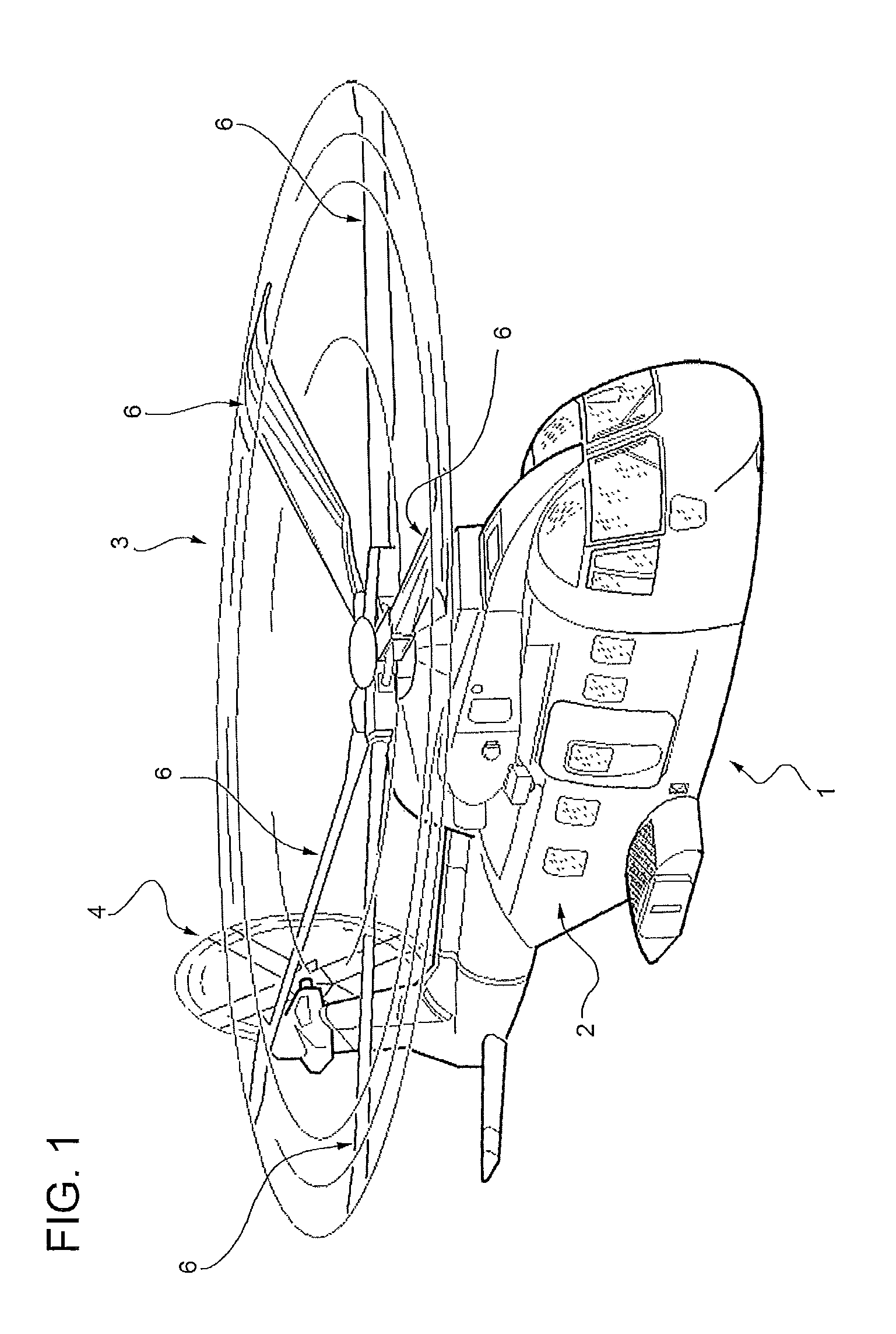
[0025]Number 1 in FIG. 1 indicates as a whole an aircraft capable of hovering—in the example shown, a helicopter.

[0026]Helicopter 1 substantially comprises a fuselage 2; a main rotor 3 mounted for rotation on the top of fuselage 2 to sustain helicopter 1 as a whole; and a tail rotor 4 fitted to the rear end of fuselage 2 and rotating in a plane crosswise to that of rotor 3 to counteract the torque generated on fuselage 2 by rotor 3.

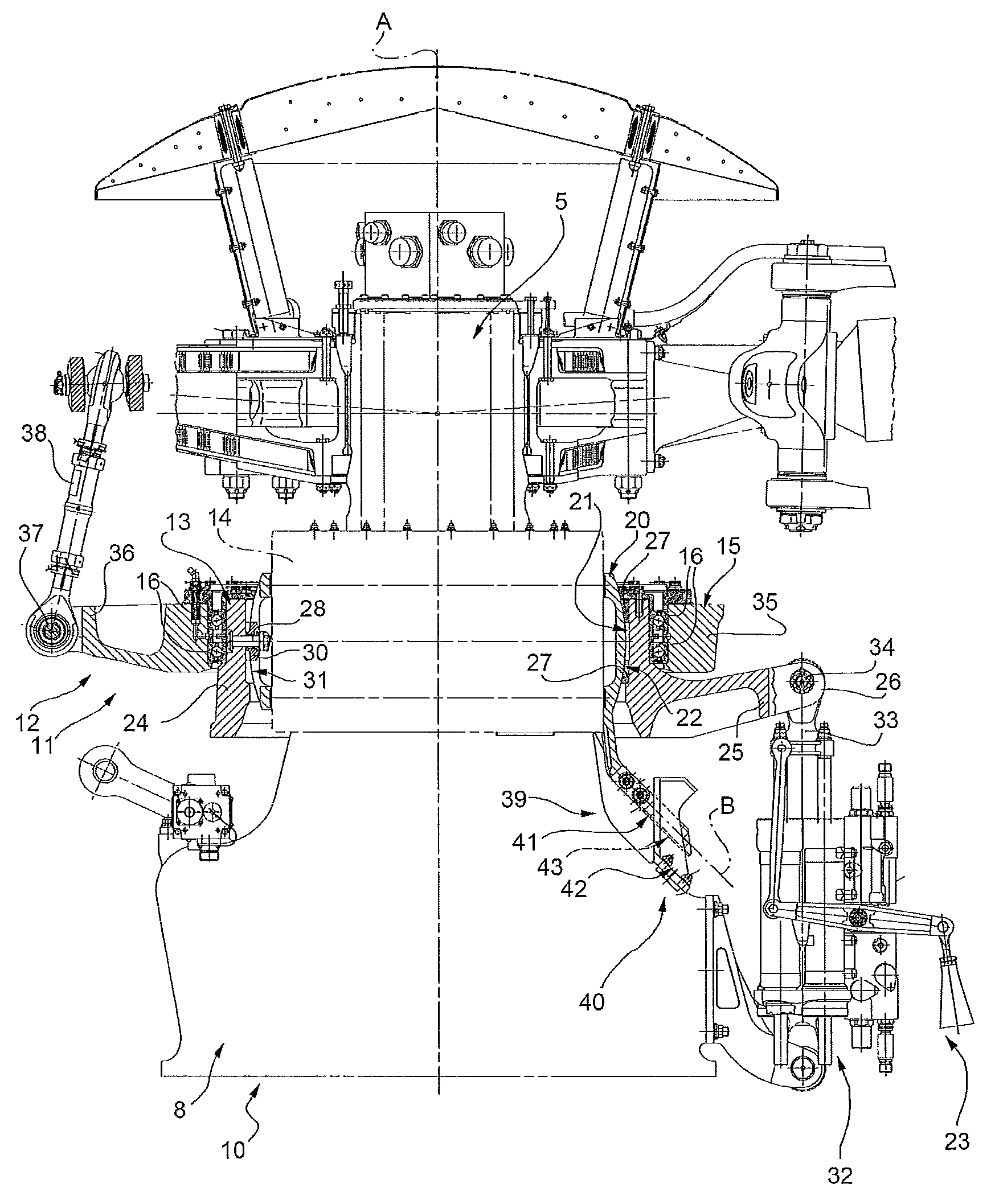
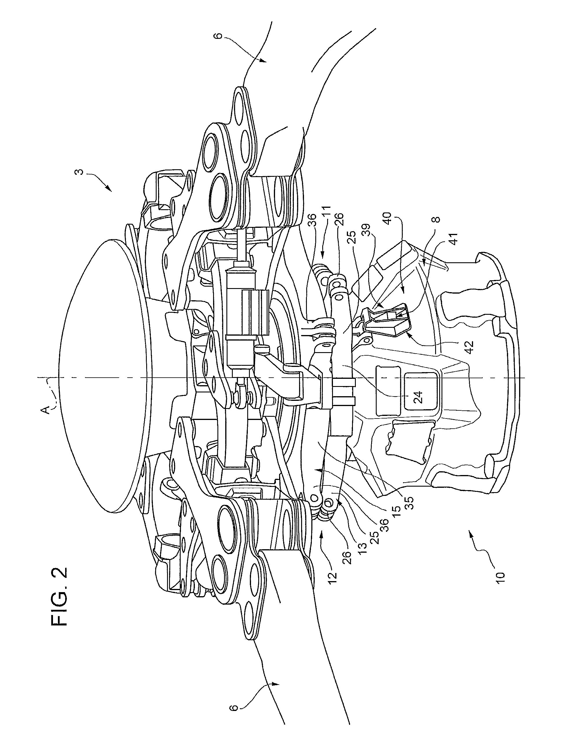
[0027]With reference to FIGS. 1-3, rotor 3 substantially comprises a drive shaft 5 of axis A, and a number of blades 6 connected in known manner to the top end of drive shaft 5, and projects from the top of a fixed housing or pylon 8 fitted in known manner (not shown) to fuselage 2. More specifically, drive shaft 5 is supported inside housing 8 by means of bearings (not shown) to rotate about axis A, extends substantially vertically, and projects outwards through an end opening in housing 8.

[0028]Rotor 3 and housing 8 together define a rotor assembly 10 i...


PUM


Abstract

A constraint assembly for an aircraft, having a first member; a second member mounted to translate along and rotate about its own axis; and connecting means for connecting the first and second member, to prevent rotation of the second member about the axis with respect to the first member; the connecting means having a retaining arm, which projects outwards from one of the first and second member, and extends at a distance of other than zero from the axis; and an antirotation bracket, which projects from the other of the first and second member, extends at a distance of other than zero from the axis, and defines a through opening engaged in sliding manner by the retaining arm.

Description

[0001]The present invention relates to a rotor assembly for an aircraft capable of hovering, such as a helicopter or convertiplane, and equipped with an improved constraint assembly.[0002]In the following description and attached drawings, reference is made, purely by way of a non-limiting example, to a helicopter rotor assembly.[0003]FIG. 8 shows a section, with parts removed for clarity, of one example of a known helicopter rotor assembly, indicated as a whole by 100.BACKGROUND OF THE INVENTION[0004]In known helicopter rotor assemblies, and particularly rotor assembly 100, cyclic and collective pitch are normally controlled by an oscillating-plate control device 101 substantially comprising two concentric rings 102, 103. The outer ring 102, i.e. the one radially outermost with respect to the central axis A, is supported for rotation, on bearings 104, by the inner ring 103, and is connected angularly to a drive shaft 105 to rotate a number of pitch-change rods 107, each hinged ecce...

Claims


Application Information

Patent Timeline
Patent Type & Authority Patents(United States)
IPC IPC(8): B64C27/605B64C27/32
CPCB64C27/605B64C27/32B64C27/51B64C27/54
Inventor PURICELLI, GIOVANNI
Owner LEONARDO FINMECCANICA SPA
Why Eureka
Try Eureka