Method of improving fault tolerance in a computing system arranged to find a computational solution

a computing system and fault tolerance technology, applied in computing, error detection/correction, instruments, etc., can solve problems such as large amount of computation having to be repeated, large amount of computation, and high cost of replication of work, so as to reduce the risk of failure, less communication, and less accurate solutions

Active Publication Date: 2016-02-16
FUJITSU LTD
View PDF12 Cites 0 Cited by
  • Summary
  • Abstract
  • Description
  • Claims
  • Application Information

AI Technical Summary

Benefits of technology

[0048]For load-balancing or other purposes, the less accurate solver can execute on a different number of processing units than the more accurate solver, such as fewer processing units. This arrangement has the additional advantage that the less accurate solution may be less vulnerable to failure because it requires less communication between processing units.
[0049]As mentioned above, the less accurate solver is likely to require fewer computing resources, and thus execute more quickly than a solver higher in the hierarchy when using the same number of processing units. The execution speed of the two solvers can be made more consistent by dividing the more accurate solver execution into more parallel processes. Thus each solver may execute in a number of processes hosted on the computing system, the less accurate solver being split into fewer processes. To reduce redundancy, the difference between the solvers can be such that less accurate solver processes account for less than 20%, more preferably less than 10%, most preferably less than 1% of the total number of processes for both solvers.
[0057]Incidentally, for such iterative solvers with periodic synchronization between the fast and the accurate solvers, it is still advantageous to replace any missing value in the less accurate (fast) solvers, even though all the values will be refreshed at the end of the loop. The fast solver will need these values to continue to compute its approximation and these will be required in the event of any failures in the accurate solver before the refresh.

Problems solved by technology

There are problems with each of these prior art methods.
An automatic MPI response to a fault may not be optimal for a particular application, so a developer may prefer to retain control of how faults are dealt with.
Checkpointing (especially on very large systems) is time consuming and—if a fault occurs just before a checkpoint is due (or during a checkpoint)—may result in a large amount of computation having to be repeated.
Replication of work is also expensive—and if the entire program function must be duplicated for fault resilience then, in effect, the available computing power is halved.
Task pools with reassignment avoid the need to duplicate so much work, but for some applications (especially the very large applications expected to run on exascale systems) it may not be possible to break the work up into sufficiently fine-grained independent tasks.
A component failure in any one grid reduces the accuracy of the combined solution, but only within a known tolerance.
However, there are drawbacks to this method also.
This is not necessarily the case for a general application.Failure of one node leads to other nodes also being unable to contribute to the solution (and nodes computing the solution on the coarse grid which the faulty node was working on are unused).
Such methods cannot, however, be immediately applied to applications that are not based on a grid (e.g. particle-based methods used in computational fluid dynamics (CFD) or computational chemistry).
The inventor has come to the realization that the main technical issue relating to fault-tolerant application execution relates to loss of data when a node or other processing unit fails.
This leads to the inability to communicate this data.
A second technical issue relates to completion of the computation that the application is expecting to be carried out on the failed process.
In general, these are based on automated checkpoint-restart technology and message-logging and result in a slowdown of application execution.
However, other processes can instead compute a “fast” (less accurate) version of the solution.
In one example, the less accurate solver can have the same discretization of the problem, but use a faster (and less accurate) time-stepping method.
As mentioned above, the less accurate solver is likely to require fewer computing resources, and thus execute more quickly than a solver higher in the hierarchy when using the same number of processing units.
However, since the solver(s) lower in the hierarchy are not used for the final solution, some usual constraints applied to selecting a solver need not apply.
In some embodiments it is due to miscommunication between processing units of the computing system or due to a failed computation at a processing unit of the computing system.

Method used


Image

  • Method of improving fault tolerance in a computing system arranged to find a computational solution
  • Method of improving fault tolerance in a computing system arranged to find a computational solution
  • Method of improving fault tolerance in a computing system arranged to find a computational solution

Examples


Embodiment Construction

[0087]Reference will now be made in detail to the embodiments, examples of which are illustrated in the accompanying drawings, wherein like reference numerals refer to the like elements throughout. The embodiments are described below to explain the present invention by referring to the figures.

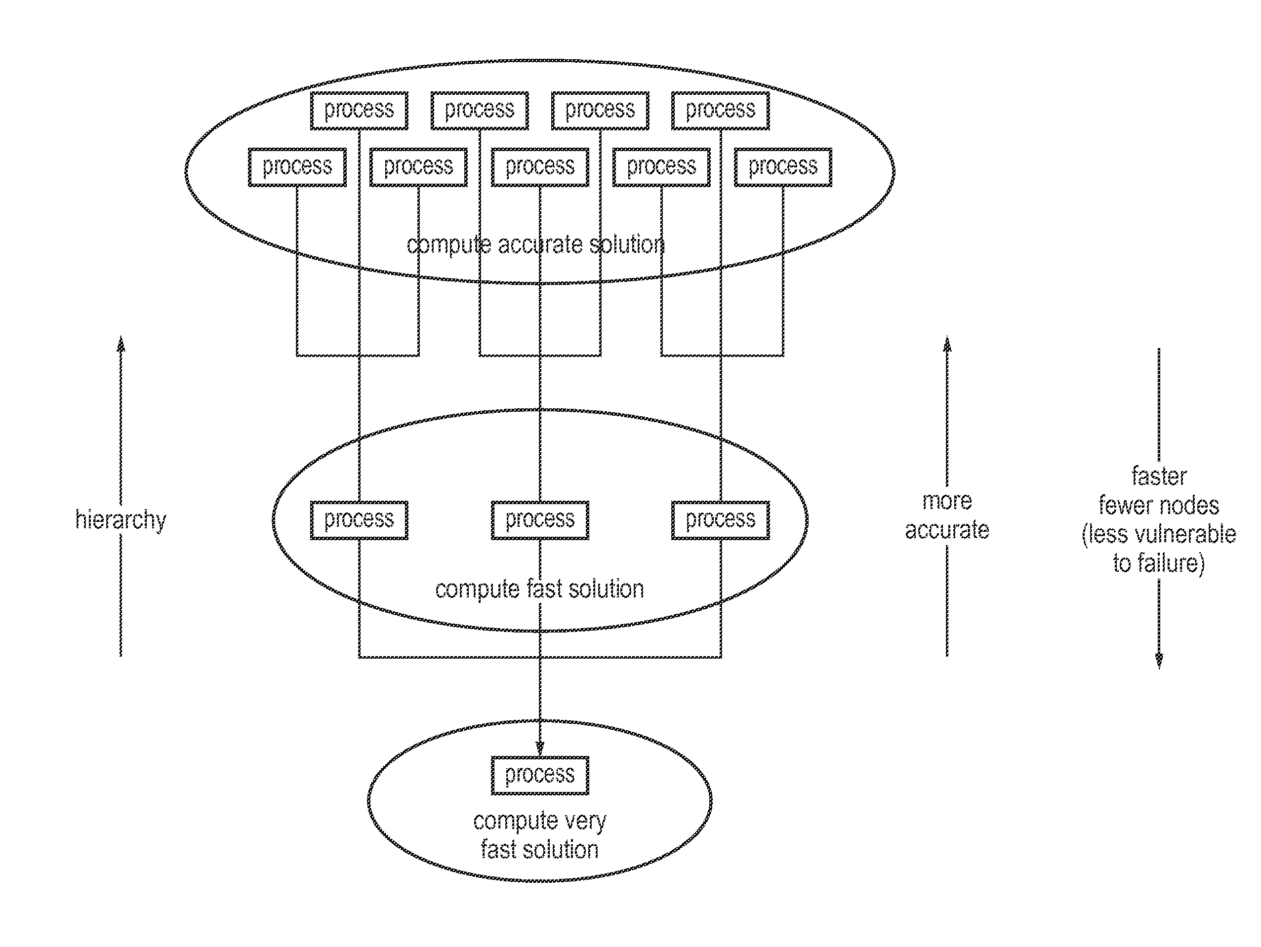
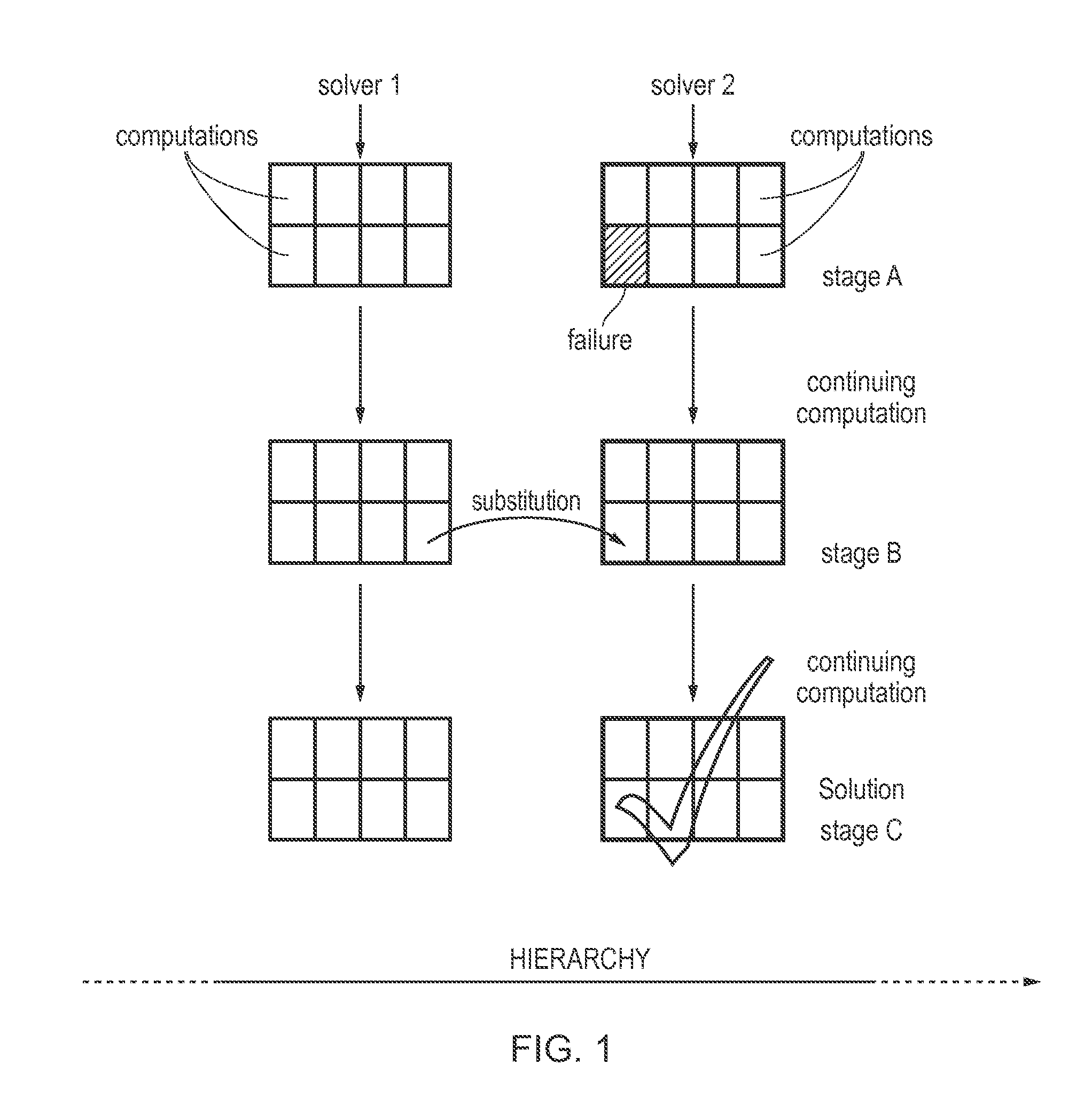
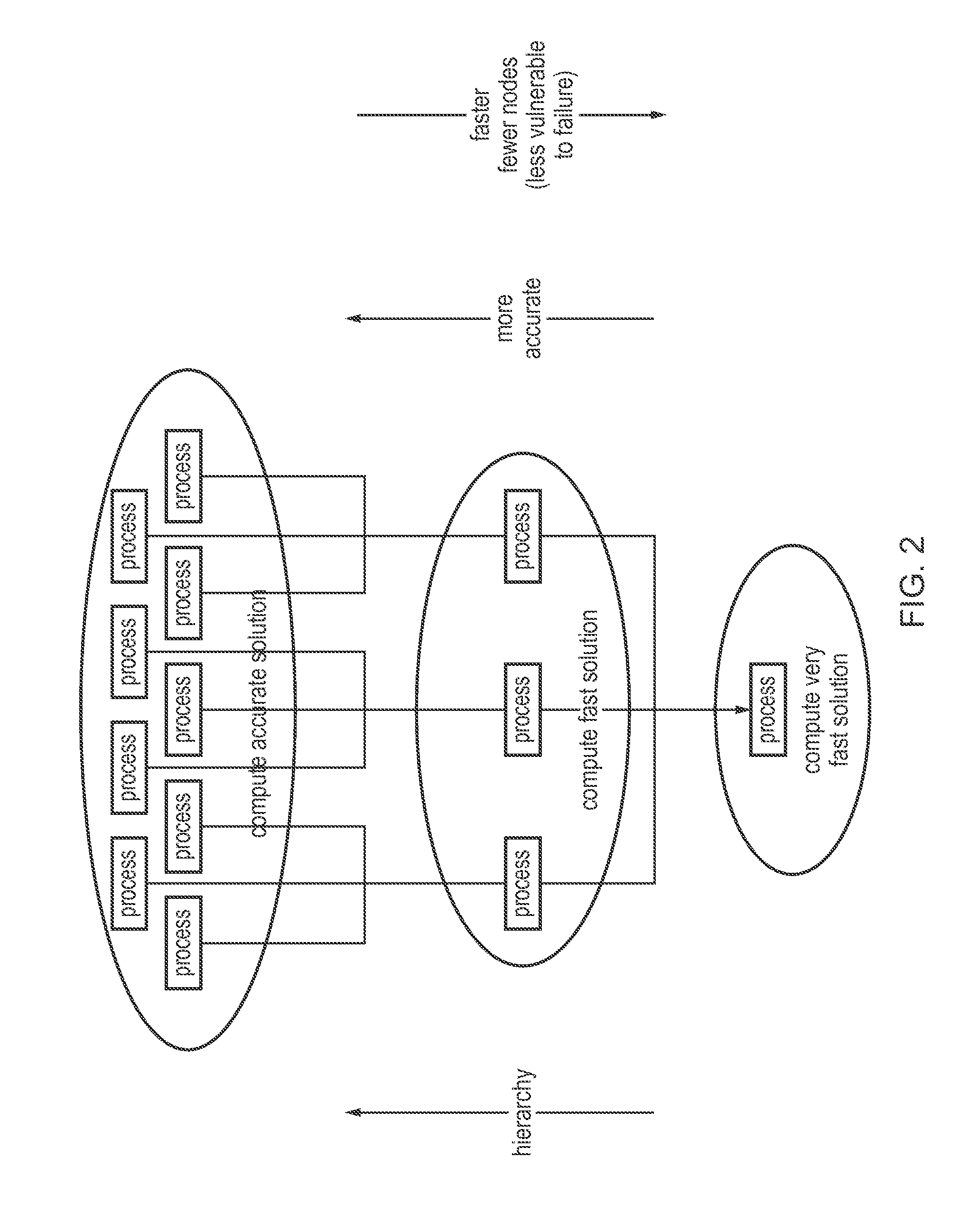
[0088]FIG. 1 is an overview diagram of two different solvers according to invention embodiments. Solver 1 is shown to the left and solver 2 to the right. Other solvers may be present within the hierarchy, as illustrated by the dotted lines of the hierarchy arrow to the left and right of Solvers 1 and 2. Solver 2 is higher in the hierarchy, and its results are thus to be used for the computational solution. It is shown in bold, and is assumed to be better in some way, by dint of higher, accuracy, complexity reliability etc.

[0089]At stage A, shown at the top of the figure, both solvers are carrying out computations. This is shown by the division of a block into cells, although no particular refe...


PUM


Abstract

A method of improving fault tolerance in a computing system arranged to find a computational solution, the method comprising: computing at least two versions of the solution by using a hierarchy of at least two different solvers in parallel; and if there is a fault during execution of a solver resulting in a missing value, substituting a value from a solver that is lower in the hierarchy to replace the missing value.

Description

CROSS-REFERENCE TO RELATED APPLICATIONS[0001]This application claims the benefit of European Application No. 13168261.9, filed May 17, 2013, the disclosure of which is incorporated herein by reference.BACKGROUND[0002]1. Field[0003]The present invention relates to fault resilience in computing systems. Fault-resilient computer programs are required in a wide range of application areas, for instance from simple computations to image rendering and large-scale, complex simulations, including on-the-fly and offline processing. As one important example, mission-critical jobs (e.g. operational weather forecasting) or systems (e.g. the internet) must be resilient to failure. This invention addresses the whole gamut of these application areas, and is focused particularly on distributed, parallel computer programs running on very large high-performance computing systems with data distributed over a number of CPUs.[0004]2. Description of the Related Art[0005]Computationally intense application...

Claims


Application Information

Patent Timeline
Patent Type & Authority Patents(United States)
IPC IPC(8): G06F11/00G06F11/14
CPCG06F11/1415G06F11/1479
Inventor SOUTHERN, JAMES, ALASTAIR
Owner FUJITSU LTD
Why Eureka
Try Eureka