
Primary fuselage structure for aircraft including struts capable of early failure to increase the absorption of energy in the event of a crash

a technology of fuselage structure and strut, which is applied in the direction of fuselage, fuselage, transportation and packaging, etc., can solve the problems of reducing the permissible load on the lower floor, undesirable increase in the overall mass of the primary structure of the fuselage, and surplus performance of airplanes using these composite materials, etc., to achieve simple, economical and effective solutions.

Active Publication Date: 2016-02-23
AIRBUS OPERATIONS (SAS)
View PDF6 Cites 0 Cited by
  • Summary
  • Abstract
  • Description
  • Claims
  • Application Information

AI Technical Summary

Benefits of technology

The invention aims to provide a simple, affordable, and effective solution to overcome these problems. This would at least partially avoid the disadvantages associated with them.

Problems solved by technology

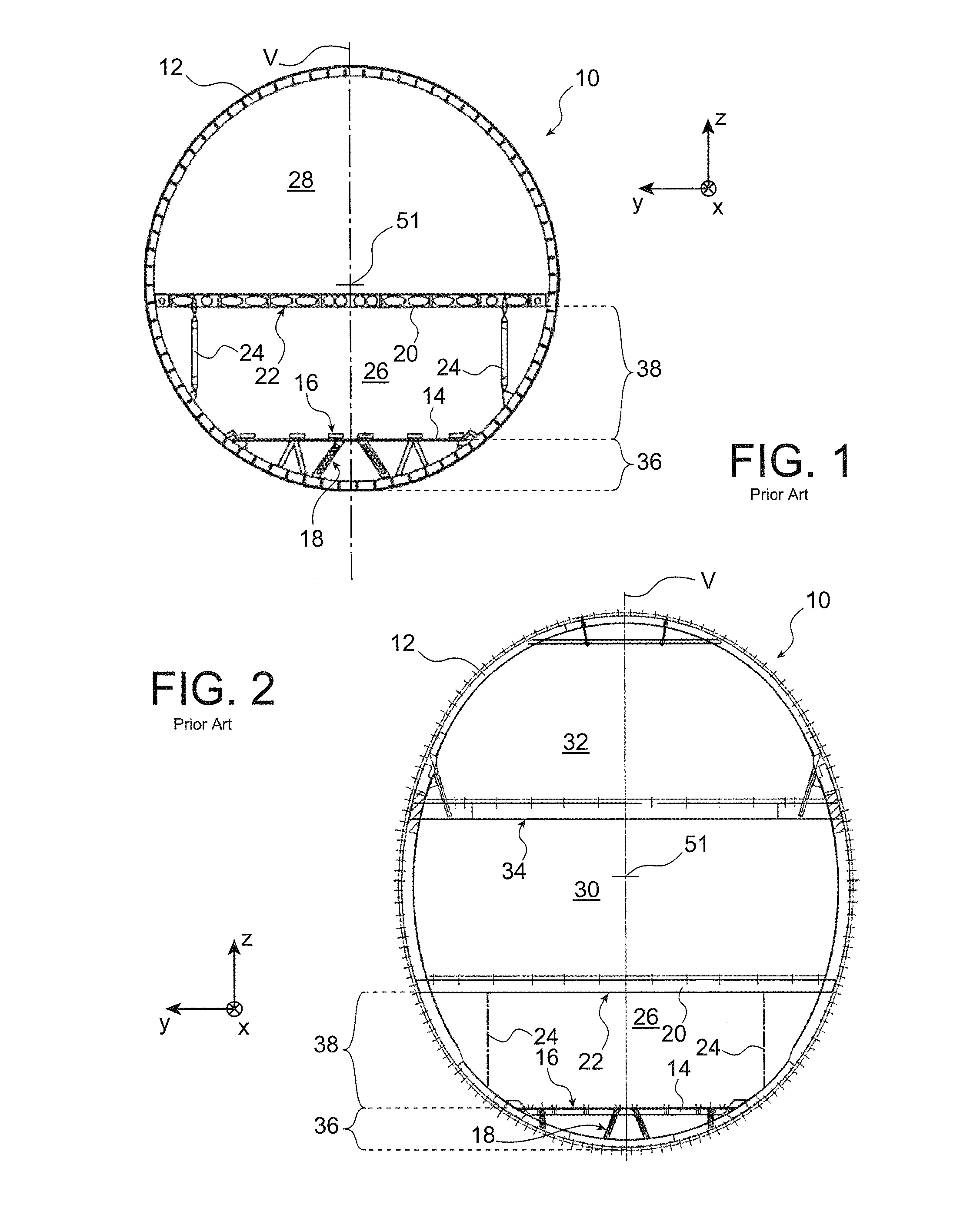
Reducing the stiffness of the struts 18 supporting the lower floor structure 16 would allow a reduction in the level of the forces transmitted to the second portion 38 of the primary structure in the event of a crash, but this solution is not satisfactory because it necessarily results in a reduction of the permissible load on the lower floor during normal operation of the airplane.
Thus this solution necessitates overdimensioning of the struts, which leads to an undesirable increase in the overall mass of the primary structure of the fuselage.
However, the use of composite materials in airplane construction is becoming general due to the fact that these materials allow great stiffness to be obtained with low mass, offering the airplane using these composite materials a performance surplus compared with an airplane made of metallic materials.
However, use of these composite materials does not allow these structural elements to deform plastically as elements made of metal do.
On the contrary, when they are subjected to a large impact, these elements generally undergo explosive failure, resulting in a relatively low level of absorbed energy.

Method used


Image

  • Primary fuselage structure for aircraft including struts capable of early failure to increase the absorption of energy in the event of a crash
  • Primary fuselage structure for aircraft including struts capable of early failure to increase the absorption of energy in the event of a crash
  • Primary fuselage structure for aircraft including struts capable of early failure to increase the absorption of energy in the event of a crash

Examples


Embodiment Construction

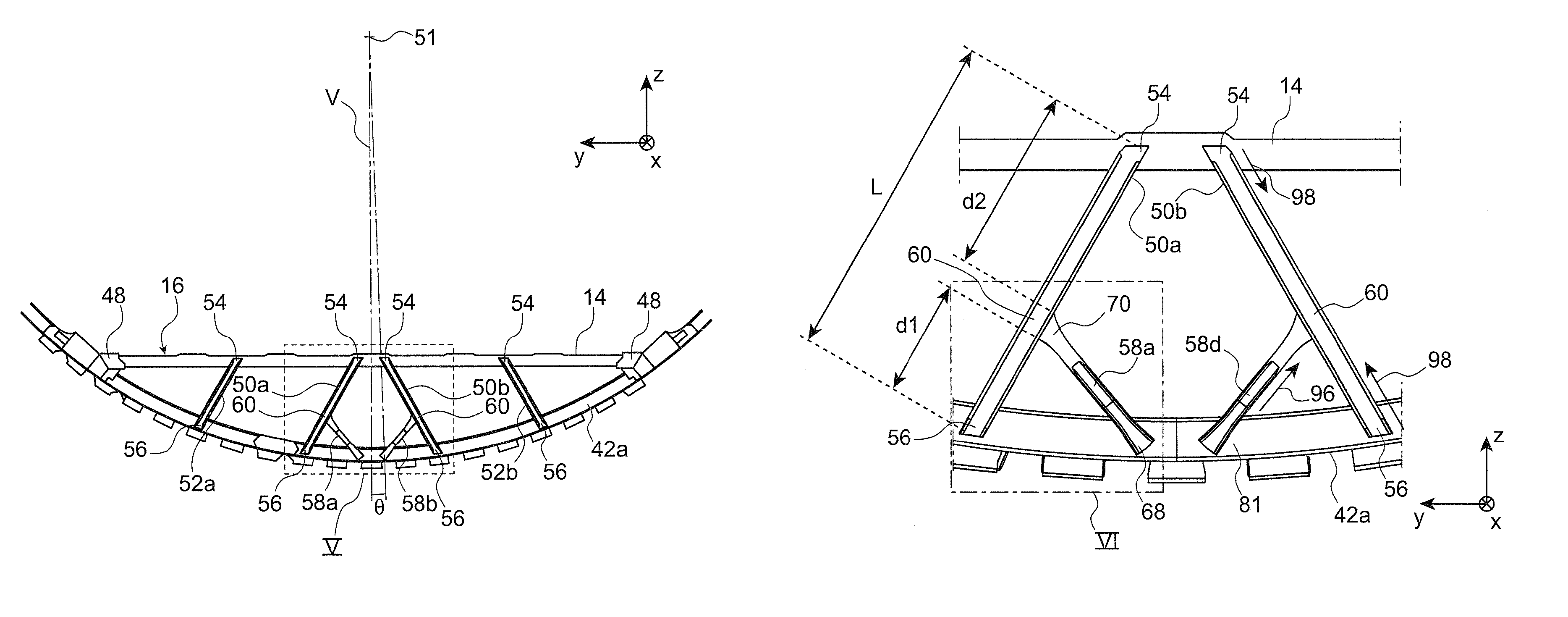
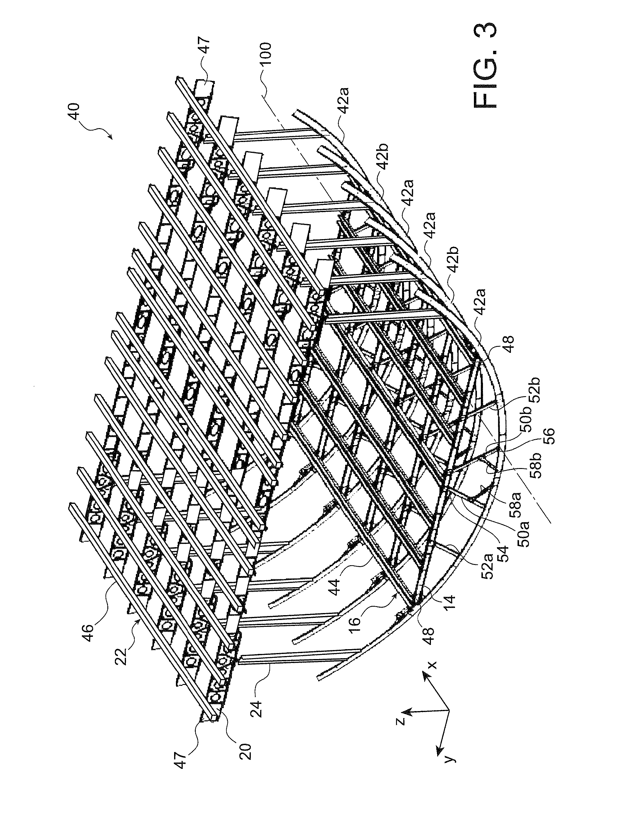
[0098]FIG. 3 illustrates a lower portion of a primary fuselage structure 40 of an airplane according to a preferred embodiment of the invention.

[0099]Throughout the present description, X designates the longitudinal direction of the primary fuselage structure 40 which can also be assimilated to the longitudinal direction of the airplane comprising this primary fuselage structure. In addition, Y designates the direction that is oriented transversely to the primary fuselage structure 40 and can also be assimilated to the transverse direction of the airplane, and Z is the vertical or height direction, these three directions X, Y and Z being mutually orthogonal.

[0100]In the example described, the fuselage of the airplane consists of several segments. FIG. 3 thus illustrates a portion of the primary structure of a segment of that fuselage.

[0101]This primary structure 40 comprises a plurality of circumferential frames 42a, 42b, of which only a lower portion is shown in FIG. 3, as well as ...


PUM


Abstract

A primary fuselage structure for an aircraft, including circumferential frames, a floor structure having lateral ends connected to the circumferential frames, at least one strut supporting the floor structure and including a lower end fixed on a circumferential frame and an upper end fixed on the floor structure, and at least one failure-initiating element associated with the strut, including a first arrangement for fastening the strut to a circumferential frame, at a distance from the lower end of the strut, as well as a second arrangement for attaching the circumferential frame to the strut, away from the ends of the strut. A fuselage segment and aircraft, such as an airplane, including the primary fuselage structure are also provided.

Description

CROSS-REFERENCES TO RELATED APPLICATIONS[0001]This application claims the benefit of the French patent application No. 12 56180 filed on Jun. 28, 2012, the entire disclosures of which are incorporated herein by way of reference.FIELD OF THE INVENTION[0002]The present invention relates generally to dissipation of impact energy resulting from a crash of an aircraft by a lower part of the primary structure of the aircraft fuselage, in order to give the best possible protection to the passengers of the aircraft.[0003]It thus relates to a primary aircraft fuselage structure capable of dissipating the energy resulting from such a crash, particularly when the impact relates to a lower region of the fuselage.[0004]The invention can be advantageously applied to primary fuselage structures which are made at least in part of composite materials.[0005]It is designed particularly to be applied to fuselages of airplanes, particularly medium- and high-capacity airliners.BACKGROUND OF THE INVENTION...

Claims


Application Information

Patent Timeline
Patent Type & Authority Patents(United States)
IPC IPC(8): B64C1/06
CPCB64C1/062
Inventor MILLIERE, JEROMEFAURE, JEAN-MARCFROGER, EDMONDREKERT, CHRISTIANMONLOUIS-BONNAIRE, SANDRINE
Owner AIRBUS OPERATIONS (SAS)
Learn More