Lid for vacuum cooking pot and cooking pot using same

a vacuum cooking pot and lid technology, applied in the field of vacuum cooking pots, can solve the problem that the lid cannot be erected, and achieve the effect of preventing condensation of water drops, reducing the bottle neck effect, and being protected from being messy

Active Publication Date: 2016-03-01
HAPPYCALL
View PDF47 Cites 85 Cited by
  • Summary
  • Abstract
  • Description
  • Claims
  • Application Information

AI Technical Summary

Benefits of technology

[0033]A vacuum function and an overflow prevention function can be implemented with one lid handle by disposing the check valve in the center of the lid handle.
[0034]By further forming an arm in the lid handle, three functions such as a vacuum function, an overflow prevention function, and a leg function when erecting the lid can be implemented with one lid handle.
[0035]Besides, by further disposing a flange above the open-close flange of the check valve, the flange provides a function of blocking the overflowed soup passing through the open-close flange to some degree,
[0036]In addition, multiple holes formed in said flange reduce the bottle neck effect of the steam exhausting between the inside of the central hole cap unit and the flange therefore it prevents condensation of water drops; the surroundings can be protected from being messy, and burns or the like can be prevented by avoiding the splashing of the water drops due to condensation.
[0037]In addition, by installing a guide piece in the central hole cap unit, concerns of getting burn for a user are eliminated by guiding the steam towards upward direction not to direction towards the arm (radial direction of the lid).

Problems solved by technology

However, the check valve (or the vacuum release valve) of the prior art is made separately from the lid handle, and the handle is holdably formed in the center of the lid therefore the lid cannot be erected.

Method used


Image

  • Lid for vacuum cooking pot and cooking pot using same
  • Lid for vacuum cooking pot and cooking pot using same
  • Lid for vacuum cooking pot and cooking pot using same

Examples


Embodiment Construction

[0054]Hereinafter, a preferred exemplary embodiment of the present invention will be described in detail with reference to the accompanying drawings.

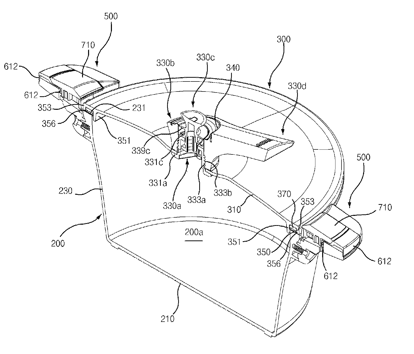
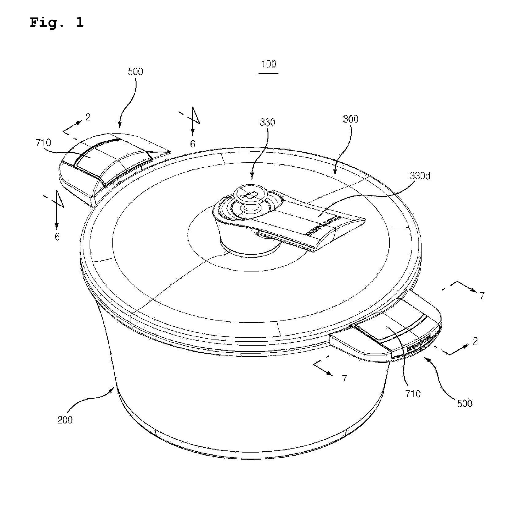
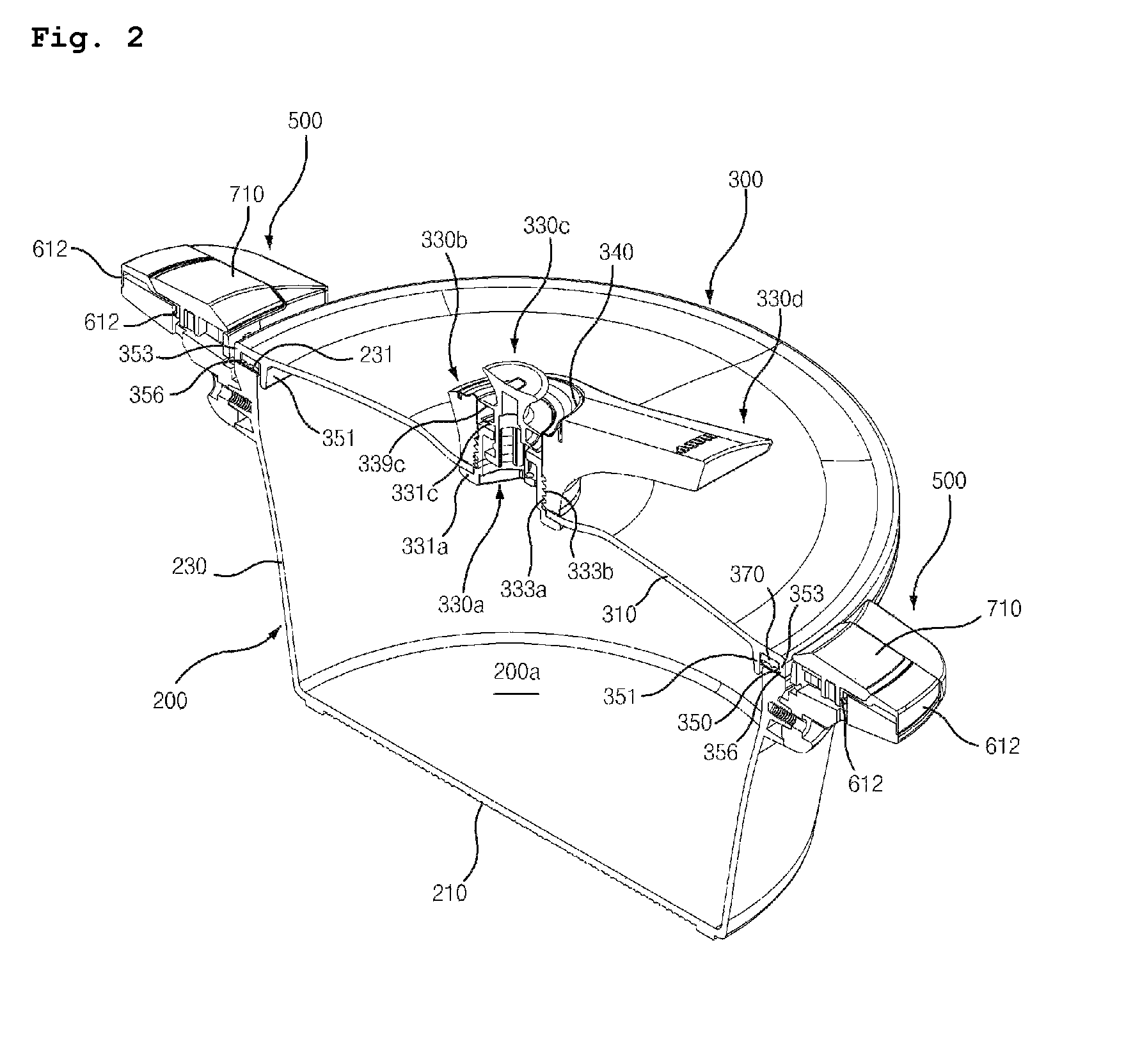
[0055]FIG. 1 is a perspective view illustrating a vacuum cooking pot according to a preferred exemplary embodiment of the present invention; FIG. 2 is a cross-sectional view along the line 2-2 in FIG. 1; FIG. 3 is an exploded perspective view illustrating the lid in FIG. 1; FIG. 4a is a cross-sectional view of a check valve when vacuum is maintained; FIG. 4b is a cross-sectional view of a check valve when overflow prevention is maintained in accordance with the pressure; FIG. 4c is a cross-sectional view of a check valve when it is always opened; FIG. 5 is an exploded perspective view illustrating a container in FIG. 1; FIG. 6 is a cross-sectional view along the line 6-6 in FIG. 1; FIG. 7 is a cross-sectional view along the line 7-7 in FIG. 1; FIG. 8 is a perspective view illustrating another check valve according to another exemplary e...


PUM


Abstract

A lid handle having vacuum and overflow prevention function is installed in a lid for a vacuum cooking pot, the lid being locked to a container using a locking member installed in a container handle. The lid handle may have a check valve having an open-close flange, a top unit, a central hole flange, a connecting section connecting the open-close flange with the central hold flange to form a relief path, and a flange formed in between the top unit and the open-close flange. The locking member may include a locking slider, a guide member for guiding the locking slider, and an elastic clip that determines the position of the locking slider.

Description

TECHNICAL FIELD[0001]The present invention relates to a vacuum cooking pot, wherein a lid handle having vacuum and overflow prevention function is installed in a lid for the vacuum cooking pot, and the lid is being locked to a container using a locking member installed in a container handle.BACKGROUND ART[0002]A vacuum cooking pot of the prior art can be used as a regular pot by exhausting the air through the check valve (or the vacuum release valve) due to the internal expansion of the cooking chamber during boiling.[0003]When it is cooled down after boiling, the inflow of the external air through the check valve (or the vacuum release valve) is blocked due to the internal contraction of the cooking chamber, and performs so called pumping-like function that pulls the lid to downwards direction and creates a vacuum inside such that the lid is stuck to the container thereby preventing separation thereof.[0004]When the contents is stored as it is under a vacuum, spoiling of the food c...

Claims


Application Information

Patent Timeline
Patent Type & Authority Patents(United States)
IPC IPC(8): A47J27/08B65D45/16B65D51/16B65D81/20A47J36/06F16J15/02A47J27/092
CPCA47J27/08A47J27/0804A47J27/092A47J36/06B65D45/16B65D51/1644B65D81/2015B65D2525/284B65D2525/287B65D2543/00879B65D2543/00972F16J15/028
Inventor LEE, HYUN, SAM
Owner HAPPYCALL
Why Eureka
Try Eureka