
Image forming apparatus

a technology developer roller, which is applied in the field of image forming apparatus, can solve the problems of above-mentioned electro-photographic image forming apparatus, but may not be equipped with a mechanism to detect the condition of the developer roller

Active Publication Date: 2016-03-01
BROTHER KOGYO KK
View PDF7 Cites 1 Cited by
  • Summary
  • Abstract
  • Description
  • Claims
  • Application Information

AI Technical Summary

Benefits of technology

[0008]The present invention is advantageous in that an image forming apparatus capable of detect the condition of the developer roller, which is one of being in contact with and separated from a photosensitive member, is provided.

Problems solved by technology

The above-mentioned electro-photographic image forming apparatus, however, may not be equipped with a mechanism to detect a condition of the developer roller: as to whether the developer roller is in contact with or separated from the photosensitive drum.
Therefore, there is a risk that an action, which should be performed when the developer roller is separated from the photosensitive drum, may be performed when the developer roller is actually in contact with the photosensitive drum, or vice versa.

Method used


Image

  • Image forming apparatus
  • Image forming apparatus
  • Image forming apparatus

Examples


second embodiment

10. Second Embodiment

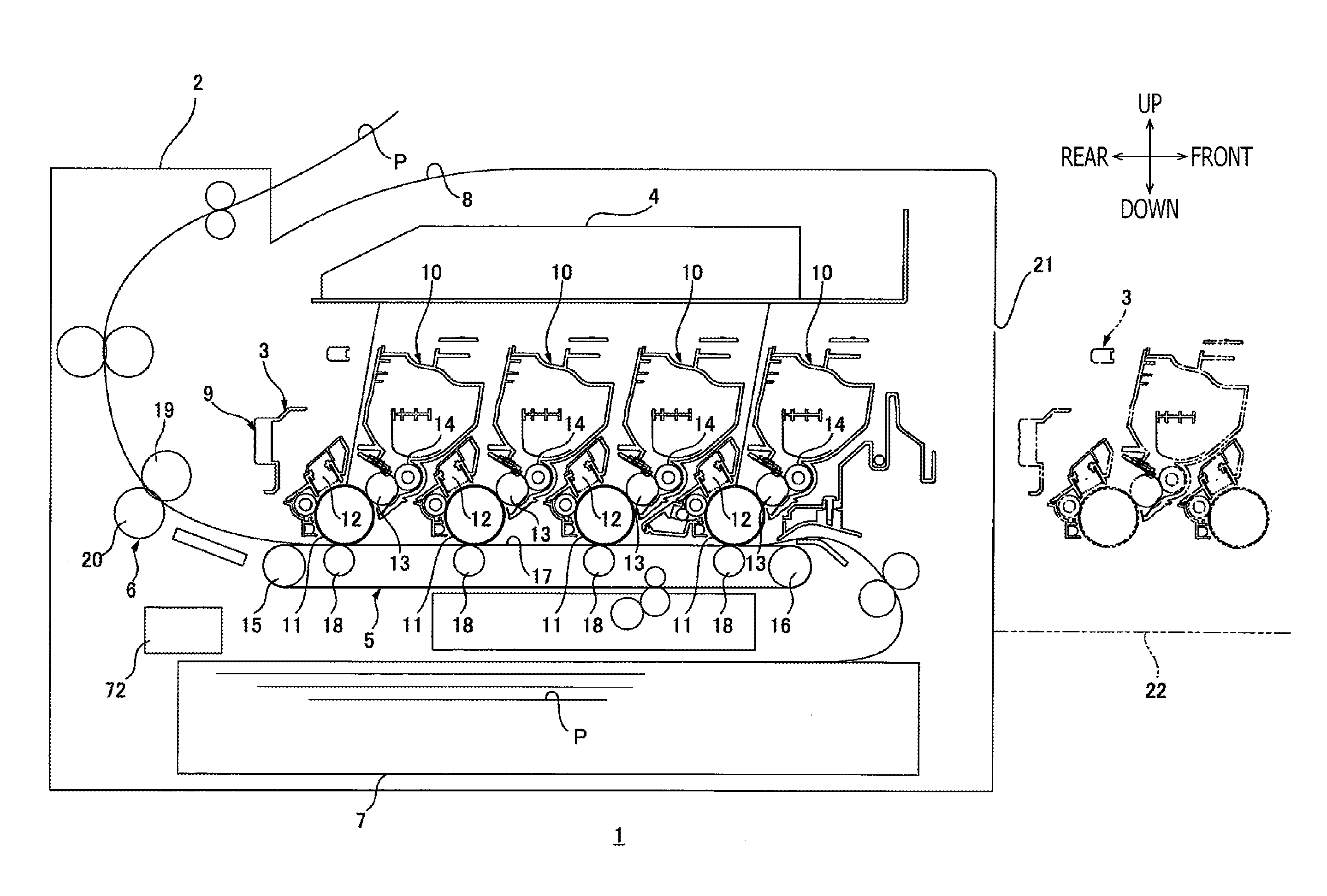
[0194]A second embodiment of the present invention will be described with reference to FIGS. 13-18. In the second embodiment described below, items or structures which are the same as or similar to the items or the structures described in the previous embodiment will be referred to by the same reference signs, and description of those will be omitted.

[0195]10.1 Overall Configuration of the Printer in the Second Embodiment

[0196]In the first embodiment described above, the printer 1 is equipped with the drum unit 9 having the photosensitive drums 11, the developer rollers 13, and the developer cartridges 10 detachably attached to the drum unit 9. Meanwhile, the printer 1 in the second embodiment is equipped with processing cartridges 91, each of which is configured to have a drum unit 92 containing the photosensitive drum 11 and developer unit 93 containing the developer roller 13 integrally.

[0197]10.2 Configuration of the Processing Cartridge

[0198]Each of the pro...


PUM


Abstract

An image forming apparatus, including a main body and a cartridge configured to be detachably attached to the main body, is provided. The cartridge includes a photosensitive member configured to carry an image formed in a developer agent thereon, a movable mechanism, and a developer roller configured to supply the developer agent to the photosensitive member. The movable mechanism is configured to shift between a first state, in which the developer roller is placed in a contact position to contact the photosensitive member, and a second state, in which the developer roller is placed in a separated position to be separated from the photosensitive member. The main body includes a detectable member configured to detect a state of the movable mechanism between the first state and the second state.

Description

CROSS REFERENCE TO RELATED APPLICATION[0001]This application claims priority from Japanese Patent Application No. 2013-221800, filed on Oct. 25, 2013, the entire subject matter of which is incorporated herein by reference.BACKGROUND[0002]1. Technical Field[0003]An aspect of the present invention relates to an image forming apparatus capable of forming an image in an electro-photographic method.[0004]2. Related Art[0005]An image forming apparatus configured to form an image in an electro-photographic method is known. The conventionally known image forming apparatus may be equipped with a removable processing cartridge, which is capable of storing a toner therein. The processing cartridge may be configured to have a drum unit and a developer unit integrally. The drum unit may contain a photosensitive drum, and a developer unit may contain a developer roller integrally, while the developer roller in the developer unit may be movable to be in contact with or separated from the photosens...

Claims


Application Information

Patent Timeline
Patent Type & Authority Patents(United States)
IPC IPC(8): G03G21/18G03G21/16
CPCG03G21/1676G03G21/1896G03G21/1821G03G21/1842
Inventor SHIRAKI, MASATOSHI
Owner BROTHER KOGYO KK
Learn More