Optical fiber sensing system, optical fiber sensing device, and method for detecting pipe deterioration

a technology of optical fiber sensing and optical fiber, applied in the direction of pipe protection/wear, mechanical equipment, instruments, etc., can solve the problems of high cost and time-consuming of preparing such a setting, and dispatching skilled workers

Pending Publication Date: 2022-08-04
NEC CORP
View PDF0 Cites 1 Cited by
  • Summary
  • Abstract
  • Description
  • Claims
  • Application Information

AI Technical Summary

Benefits of technology

[0011]The above-mentioned aspects offer the effect of providing an optical fiber sensing system, optical fiber sensing equipment, and a method for detecting pipe degradation that can detect the condition of pipe regardless of the substance flowing through the pipe or the structure of the pipe.

Problems solved by technology

However, this type of inspection work required skilled workers to be dispatched to the pipes for each inspection, which was costly.
Preparing such a setting was not only costly but also time-consuming.

Method used


Image

  • Optical fiber sensing system, optical fiber sensing device, and method for detecting pipe deterioration
  • Optical fiber sensing system, optical fiber sensing device, and method for detecting pipe deterioration
  • Optical fiber sensing system, optical fiber sensing device, and method for detecting pipe deterioration

Examples


first embodiment

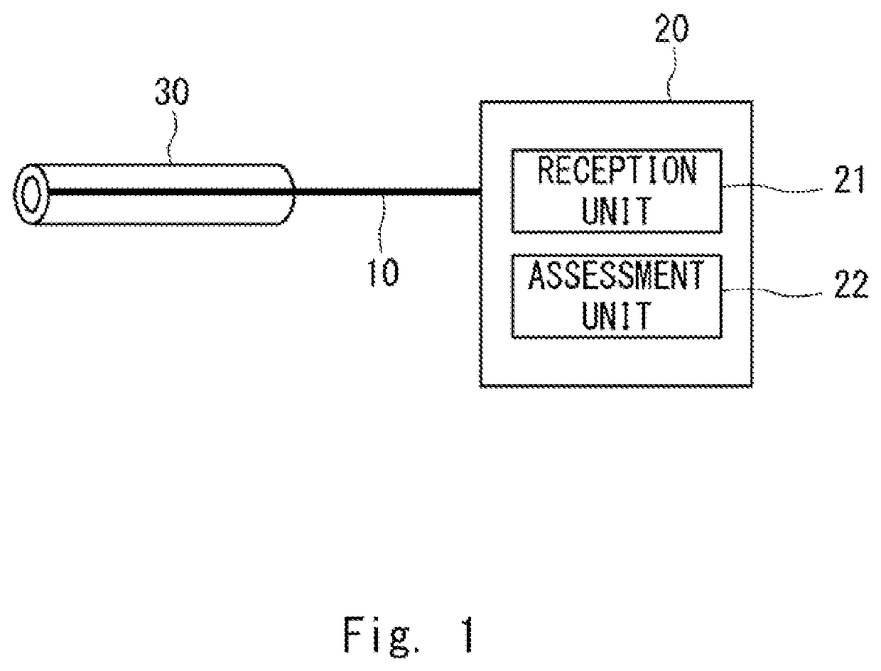
[0042]First, the following will describe a configuration example of an optical fiber sensing system according to a first example embodiment with reference to FIG. 1.

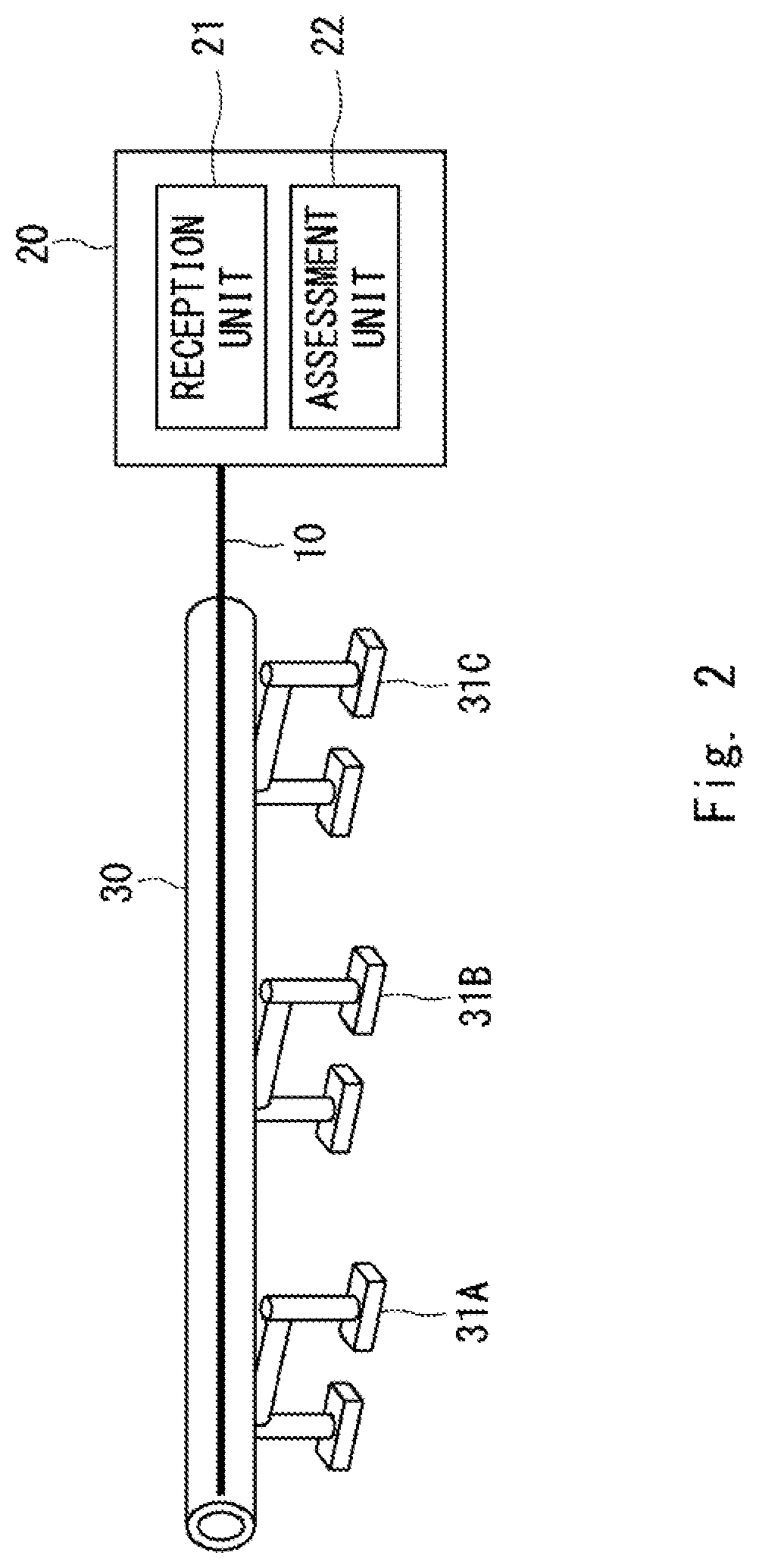
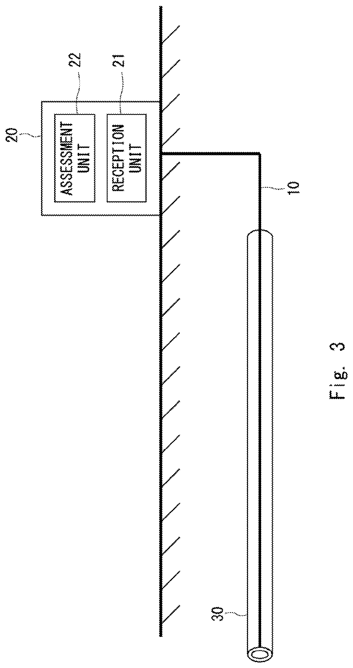
[0043]As illustrated in FIG. 1, the optical fiber sensing system according to the first example embodiment comprises an optical fiber 10 and optical fiber sensing equipment 20. Further, the optical fiber sensing equipment 20 comprises a reception unit 21 and an assessment unit 22.

[0044]The optical fiber 10 is laid in a pipe 30, and one end thereof is connected to the optical fiber sensing equipment 20. Although FIG. 1 illustrates an example in which the optical fiber 10 is passed through the inside of the pipe 30, the method of laying the optical fiber 10 is not limited thereto. For example, the optical fiber 10 may be wound around the pipe 30, or may crawl inside or outside the pipe 30 along the pipe 30. Alternatively, a sheet in which the optical fiber 10 is woven may be wound around the pipe 30. The optical fiber 10 m...

second embodiment

[0091]An optical fiber sensing system according to a second example embodiment has a similar configuration as the above-described first example embodiment, with an extended function of the assessment unit 22.

[0092]The assessment unit 22 determines the degradation state of the pipe 30 based on the vibration pattern of vibration detected by the optical fiber 10, and further detects a sign of breakage of the pipe 30 based on the determined degradation state of the pipe 30.

[0093]The following will describe examples of how the assessment unit 22 detects a sign of breakage of the pipe 30 based on the degradation state of the pipe 30.

(B1) Method B1

[0094]First, method B1 will be described.

[0095]In method B1, as illustrated in FIG. 17, the assessment unit 22 stores in advance a correspondence table indicating the time of breakage for each degradation degree of the pipe 30, which is a time when the pipe 30 having the degradation degree is predicted to break in the future.

[0096]The assessment ...

third embodiment

[0108]An optical fiber sensing system according to a third example embodiment has a similar configuration as the above-described second example embodiment, with a further extended function of the assessment unit 22.

[0109]The assessment unit 22 identifies a position where a sign of breakage of the pipe 30 is detected based on the return light received by the reception unit 21.

[0110]The following will describe examples of how the assessment unit 22 identifies a position where a sign of breakage of the pipe 30 is detected based on the returned light received by the reception unit 21.

(C1) Method C1

[0111]First, method C1 will be described.

[0112]In method C1, the assessment unit 22 first identifies the length of the optical fiber 10 from the reception unit 21 (the optical fiber sensing equipment 20) to a position where vibration occurred, based on a time difference between the time when the reception unit 21 injected pulsed light into the optical fiber 10 and the time when the reception u...


PUM

PropertyMeasurementUnit
breakage timeaaaaaaaaaa
opticalaaaaaaaaaa
timeaaaaaaaaaa

Abstract

An optical fiber sensing system according to the present disclosure comprises: an optical fiber (10) that is laid in a pipe (30); a reception unit (21) configured to receive, from the optical fiber (10), an optical signal superimposed with vibration detected by the optical fiber (10); and an assessment unit (22) configured to extract a vibration pattern of the vibration detected by the optical fiber (10) from the optical signal and determine the degradation state of the pipe (30) based on the extracted vibration pattern.

Description

TECHNICAL FIELD[0001]The present disclosure relates to an optical fiber sensing system, optical fiber sensing equipment, and a method for detecting pipe degradation.BACKGROUND ART[0002]Conventionally, inspection work of pipes that are laid in plants and the like have been often manually carried out by skilled workers. However, this type of inspection work required skilled workers to be dispatched to the pipes for each inspection, which was costly. In addition, the setting needed to be prepared for the workers to perform the inspection work. Preparation of the setting, for example, requires scaffolding when the pipes are located above ground, or excavation when the pipes are located underground. Preparing such a setting was not only costly but also time-consuming.[0003]For this reason, a technique has recently been proposed for detecting the condition of pipes without the need for workers. For example, Patent Literature 1 discloses a technique, in high-temperature gas piping consisti...

Claims


Application Information

Patent Timeline
Patent Type & Authority Applications(United States)
IPC IPC(8): G01H9/00G01N29/06
CPCG01H9/004G01N29/043G01N29/069F17D5/06F16L57/06G01D5/35358
Inventor YODA, YUKIHIDEOGURA, NAOTOAONO, YOSHIAKI
Owner NEC CORP
Why Eureka
Try Eureka