Baffling tube box, continuous flow reactor, continuous flow reaction system and control system

a technology of continuous flow and reactor, applied in the direction of process control/regulation, chemical/physical/physico-chemical processes, chemistry apparatus and processes, etc., can solve the problems of large energy consumption, severe pollution, and large size of existing straight tube reactors or u-shaped tube reactors with a large tube length, so as to improve the turbulent flow effect and reduce the size of the reactor. , the effect of large reynolds number

Active Publication Date: 2020-10-20
SHANDONG NERVE PHARMA FLUID SYST CO LTD
View PDF7 Cites 0 Cited by
  • Summary
  • Abstract
  • Description
  • Claims
  • Application Information

AI Technical Summary

Benefits of technology

[0027]The invention has the following advantages: compared with traditional reactors of the same size, the reaction flow is greatly extended, so that a large Reynolds number is obtained under a low flow velocity of reactants, and the turbulent flow effect is greatly improved; and continuous mixing can still be achieved during a continuous flow reaction, so that the condition in each reaction stage can be detected in real time, and installation and assembly are simplified.
[0028]Multiple reaction solutions are fully mixed through the mixing device, so that the reaction efficiency is improved.
[0029]The mixed reaction solution is heated in advance before entering the reactor through the preheating device and can reach a reaction temperature as soon as possible after entering the reactor, so that the reaction efficiency is improved.
[0030]The reaction conditions of the reaction system in all stages are detected in real time through the reaction control system, and accurate feedback and regulation are performed, so that all reaction conditions in the reaction system are accurately controlled.

Problems solved by technology

Reactors commonly used in the technical field of chemical pharmaceutics include tube reactors, tank reactors, and the like, wherein the tank reactors typically have a stirring device inside to mix liquid-phase reactants and are low in composition purity and reactive conversion rate, high in energy consumption and severe in pollution.
Existing straight tube reactors or U-shaped tube reactors with a large tube length are too large in size.
Traditional straight tube reactors have a poor turbulent flow effect on reactants and a small Reynolds number, which leads to a negative influence on heat-transfer and continuous mixing effects.

Method used


Image

  • Baffling tube box, continuous flow reactor, continuous flow reaction system and control system
  • Baffling tube box, continuous flow reactor, continuous flow reaction system and control system
  • Baffling tube box, continuous flow reactor, continuous flow reaction system and control system

Examples


Embodiment Construction

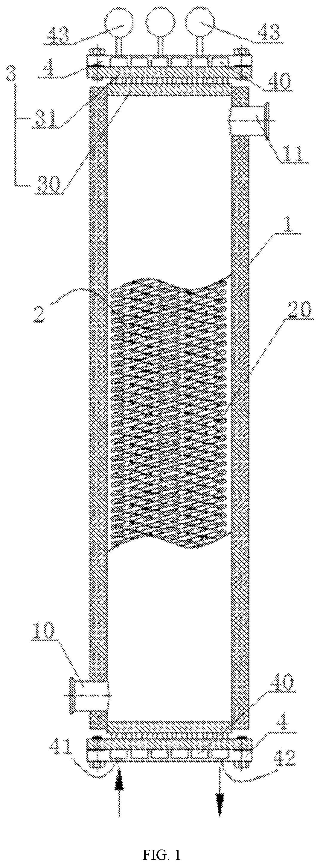
[0041]The invention is further explained below in combination with the accompanying drawings and embodiments.

[0042]The embodiments of the invention are detailed below and are illustratively shown in the accompanying drawings, and in the whole description, identical or similar reference signs represent identical or similar elements or represent elements with identical or similar functions. The embodiments described below with reference to the accompanying drawings are illustrative ones which are only used for explaining the invention, and should not be interpreted as limitations of the invention.

[0043]It should be noted that unless otherwise stated or specified, the terms “install”, “connect”, and “connection” in the description of the invention should be broadly understood. For example, “connection” may refer to fixed connection, detachable connection, integrated connection, direct connection, or indirect connection via intermediate media. Those ordinarily skilled in the art can fig...


PUM


Abstract

A continuous flow reactor includes a shell, wherein the shell is provided with a shell pass inlet and a shell pass outlet which are communicated with an inner cavity of the shell, tube plates and communication devices are connected to upper and lower ends of the shell, a reaction tube bank is arranged in the shell and includes a plurality of reaction tubes, upper and lower ends of each reaction tube are fixedly connected to the tube plates in a penetrating manner, and all the reaction tubes are sequentially communicated in series through the communication devices.

Description

[0001]This application is the National Stage Application of PCT / CN2018 / 088680, filed on May 28, 2018, which claims priority to Chinese Patent Application Nos.: CN 201720675234.5, filed on Jun. 9, 2017; CN 201710434482.5, filed on Jun. 9, 2017; CN 201710433895.1, filed on Jun. 9, 2017; and CN 201720668427.8, filed on Jun. 9, 2017, all of which are incorporated by reference for all purposes as if fully set forth herein.BACKGROUND OF THE INVENTION1. Technical Field[0002]The invention relates to the technical field of chemical pharmaceutical equipment, in particular to a baffling tube box, a continuous flow reactor, a continuous flow reaction system and a control system.2. Description of Related Art[0003]Reactors commonly used in the technical field of chemical pharmaceutics include tube reactors, tank reactors, and the like, wherein the tank reactors typically have a stirring device inside to mix liquid-phase reactants and are low in composition purity and reactive conversion rate, hig...

Claims


Application Information

Patent Timeline
Patent Type & Authority Patents(United States)
IPC IPC(8): B01J19/24B01J19/00
CPCB01J19/2405B01J19/243B01J19/006B01J2219/00087B01J2219/00033B01J2219/00177B01J2219/00772B01J19/0006B01J2219/00164B01J19/242B01J4/008B01J2219/00069B01J2219/00162B01J2219/00058B01J2219/00159B01J19/00B01J19/24
Inventor CHEN, YANKUN
Owner SHANDONG NERVE PHARMA FLUID SYST CO LTD
Why Eureka
Try Eureka