
Amplifier with variable feedback impedance

a variable impedance, amplifier technology, applied in the direction of rf amplifier, gain control, amplifier modification to reduce non-linear distortion, etc., can solve the problem that the output of the amplifier tends to become non-linear, and achieve the effect of reducing the effect of a variable impedance and maintaining the characteristic output voltage range of the rf amplifier

Active Publication Date: 2016-03-01
PSEMI CORP
View PDF14 Cites 19 Cited by
  • Summary
  • Abstract
  • Description
  • Claims
  • Application Information

AI Technical Summary

Benefits of technology

The patent text describes a way to reduce the impact of changes in the resistance of a feedback path in a radio frequency (RF) amplifier. This is accomplished by adding resistive and / or reactive components, and then using stacked transistor switches to create a variable impedance that can be controlled by the switches. This variable impedance is then connected between the output of the RF amplifier and its input, forming a feedback path that helps maintain the amplifier's characteristic output voltage range. The technical effect of this method is to improve the stability and reliability of RF amplifiers that use feedback paths.

Problems solved by technology

Unfortunately these two sought after attributes work against each other as amplifier output tends to become non-linear when operated at higher gains required for better power efficiency.

Method used


Image

  • Amplifier with variable feedback impedance
  • Amplifier with variable feedback impedance
  • Amplifier with variable feedback impedance

Examples


Embodiment Construction

[0017]Throughout this description, embodiments and variations are described for the purpose of illustrating uses and implementations of the inventive concept. The illustrative description should be understood as presenting examples of the inventive concept, rather than as limiting the scope of the concept as disclosed herein.

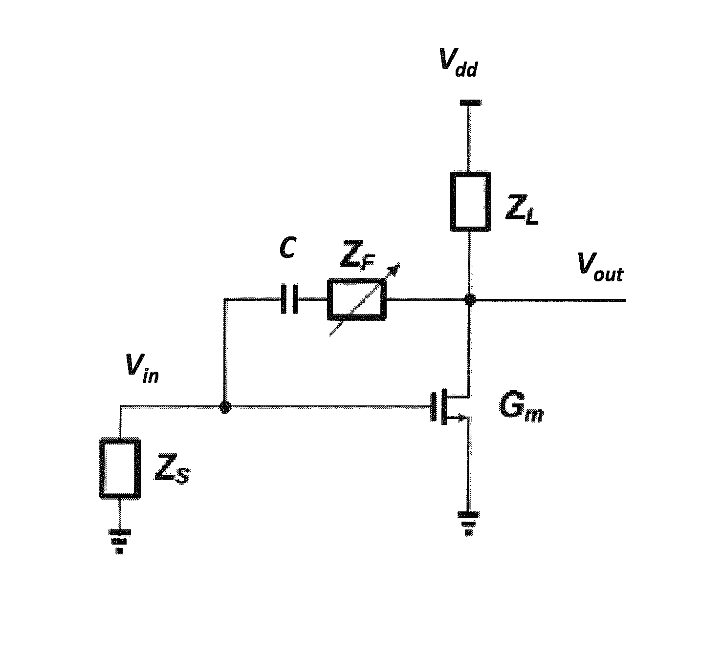
[0018]Amplifier circuits typically exhibit nonlinearities in their response which can be considered as a major nonideality, since such nonlinearities can distort asignal going through the amplifier. In particular, when considering RF applications where RF signals with sophisticated modulation schemes are transmitted, any distortion in the transmitted signal may render decoding of the received signal difficult if not impossible. For this reason, minimizing nonlinearities has been a major design issue for most RF design engineers.

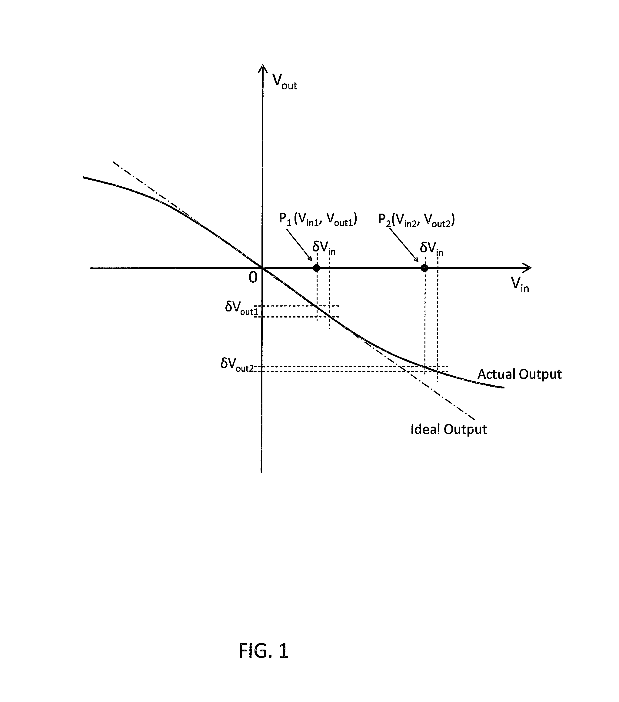
[0019]FIG. 1 shows a characteristic response of a nonlinear amplifier. The input voltage (Vin) fed to an input terminal of the nonlinear...


PUM


Abstract

A variable feedback impedance is presented capable of providing high linearity (e.g. as represented by IP2 and IP3) and high linear range (e.g. as represented by P1dB) when used in a feedback path of an RF amplifier in the presence of high voltage amplitudes.

Description

BACKGROUND[0001]1. Field[0002]The present teachings relate to radio-frequency (RF) amplifiers used in RF circuits. More particularly, the present teachings relate to methods and systems for RF amplifiers with variable feedback impedance capable of high output power and high output voltage swings while maintaining high output linearity and high output linear range.[0003]2. Description of Related Art[0004]RF amplifiers are an important part of present days RF communication systems as they constitute the main system block that drives the antenna in any radio transmitter. As such, linearity and power efficiency (e.g. gain) of such amplifiers are sought after attributes for integrators of such devices. Unfortunately these two sought after attributes work against each other as amplifier output tends to become non-linear when operated at higher gains required for better power efficiency. Feedback (e.g. using a combination of resistors, capacitors and inductors) is one of the methods univer...

Claims


Application Information

Patent Timeline
Patent Type & Authority Patents(United States)
IPC IPC(8): H03G3/20H03F1/34H03F3/195H03F1/22H03F1/32
CPCH03F1/223H03F1/3205H03F1/342H03F3/195H03F2200/451
Inventor NOBBE, DAN, WILLIAMLU, JIANHUA
Owner PSEMI CORP
Learn More