
Method and apparatus for distributed transmission power control in wireless networks

a wireless network and power control technology, applied in power management, wireless communication, radio relay systems, etc., can solve the problems of interference between the signal of each transmission node and the reception node of a neighboring link, and achieve the effect of reducing bottleneck phenomenon, improving transmission rate, and maximizing minimum transmission ra

Active Publication Date: 2016-03-01
SAMSUNG ELECTRONICS CO LTD
View PDF31 Cites 0 Cited by
  • Summary
  • Abstract
  • Description
  • Claims
  • Application Information

AI Technical Summary

Benefits of technology

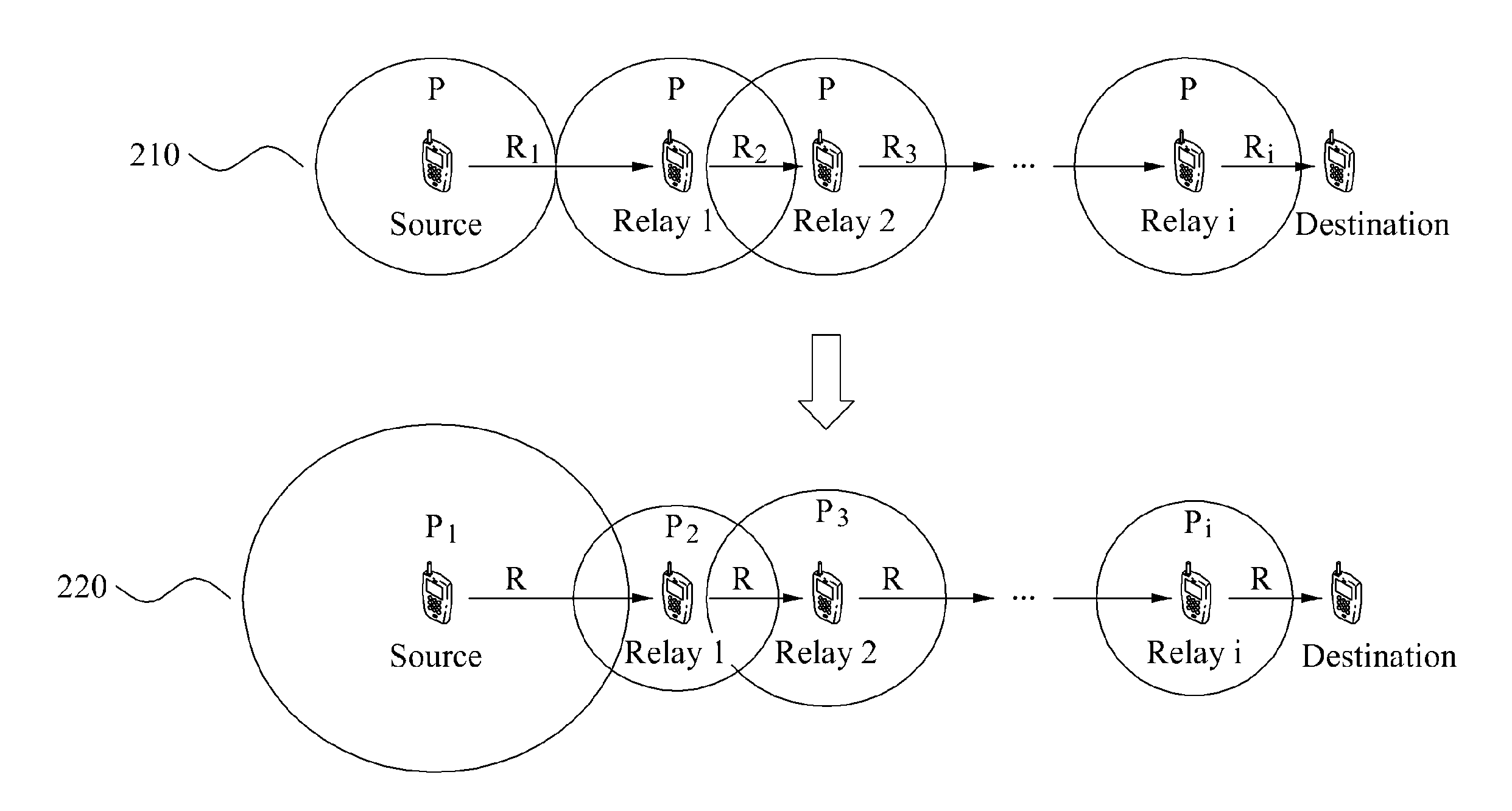
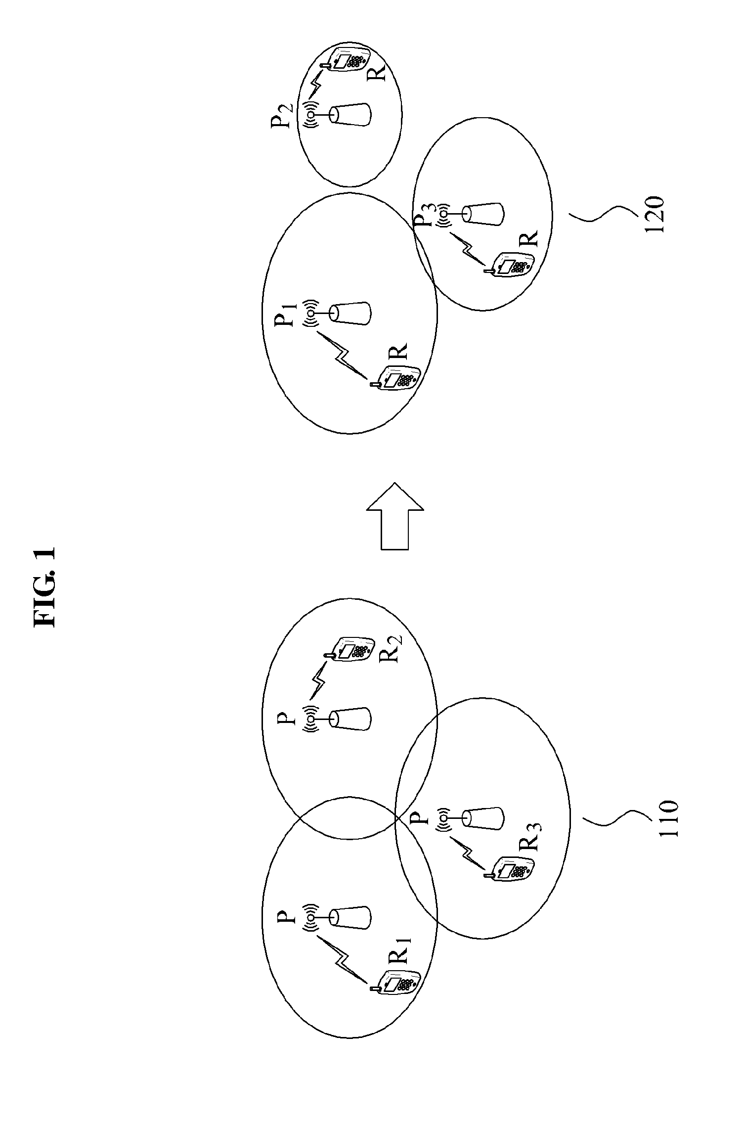
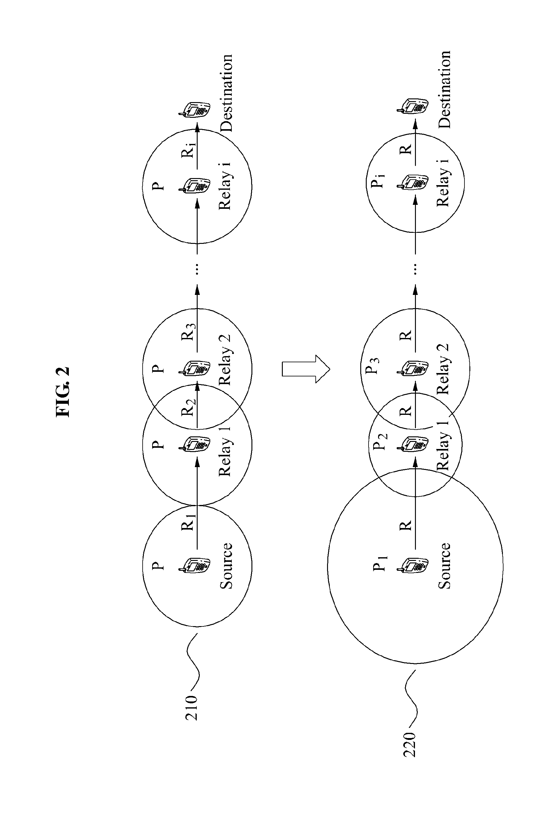
[0031]A method and apparatus for controlling a distributed transmission power according to one example may substantially maximize a minimum value of transmission rates of transmitters by controlling a transmission power of each transmitter to enable the respective transmission rates of transmitters to be substantially identical to each other. Accordingly, a bottleneck phenomenon may be reduced in an overall system that includes each transmitter. In particular, a transmission rate of a multi-hop communication system may be improved due to the reduction of the bottleneck phenomenon. Since terminals may receive power at substantially the same transmission rate in all cells, a transmission rate of broadcast control information, in each cell, may be substantially maximized.
[0032]A method and apparatus for controlling a distributed transmission power according to one example may control each transmission power so that transmission rates of transmitters may be substantially identical to each other. If the transmission rate is less than a requested transmission rate, the method and apparatus may change a resource of a transmitter that uses a substantially maximum power. Thus, a transmission rate of an overall system may be enhanced.
[0034]A method and apparatus for controlling a distributed transmission power according to one example may use a relatively simple algorithm, thereby reducing a complexity during an implementation, and may provide a control regardless of a number of nodes.

Problems solved by technology

However, a signal transmitted by each base station may interfere with a terminal in a neighboring cell.
Since a plurality of transmission nodes may simultaneously transmit data, a signal of each transmission node may interfere with a reception node of a neighboring link.

Method used


Image

  • Method and apparatus for distributed transmission power control in wireless networks
  • Method and apparatus for distributed transmission power control in wireless networks
  • Method and apparatus for distributed transmission power control in wireless networks

Examples


Embodiment Construction

[0048]The following detailed description is provided to assist the reader in gaining a comprehensive understanding of the methods, apparatuses, and / or systems described herein. Accordingly, various changes, modifications, and equivalents of the methods, apparatuses, and / or systems described herein will be suggested to those of ordinary skill in the art. The progression of processing steps and / or operations described is an example; however, the sequence of and / or operations is not limited to that set forth herein and may be changed as is known in the art, with the exception of steps and / or operations necessarily occurring in a certain order. Also, description of well-known functions and constructions may be omitted for increased clarity and conciseness.

[0049]A signal transmitted by each base station in a cellular communication system may interfere with a terminal in a neighboring cell. Thus, in a view of an overall cellular communication system, it may be inefficient to increase a tr...


PUM


Abstract

Provided is a method and apparatus for distributed transmission power control in a wireless network. The method and apparatus for distributed transmission power control may substantially maximize a minimum value of a transmission rate of each transmitter by controlling a transmission power of each transmitter. The transmission power may be controlled so that transmission rates of transmitters are substantially identical to each other. If the transmission rate is less than a requested transmission rate, the method and apparatus may change a resource of a transmitter that uses a substantially maximum power.

Description

CROSS-REFERENCE TO RELATED APPLICATION(S)[0001]This application claims the benefit under 35 U.S.C. §119(a) of Korean Patent Application No. 10-2010-0124856, filed on Dec. 8, 2010, in the Korean Intellectual Property Office, the entire disclosure of which is incorporated herein by reference for all purposes.BACKGROUND[0002]1. Field[0003]The following description relates to a method and apparatus for performing a distributed transmission power control in a wireless network. More particularly, examples are directed to a method and apparatus for controlling a transmission power of a transmitter in a cellular communication system and a multi-hop communication system.[0004]2. Description of Related Art[0005]A cellular communication system may include a plurality of cells adjacent to each other. A base station located at a center of each cell may communicate with a terminal located at a predetermined position within a corresponding cell. Each base station may determine a transmission power...

Claims


Application Information

Patent Timeline
Patent Type & Authority Patents(United States)
IPC IPC(8): H04B7/00H04B7/14H04W52/40H04W52/14
CPCH04W52/40H04W52/143H04L1/0002H04W52/241H04W52/46H04L2001/0097H04W52/32H04W52/60
Inventor CHOI, HYUN, HOSHIN, CHANG, YONGJANG, KYUNG, HUN
Owner SAMSUNG ELECTRONICS CO LTD
Learn More