Vehicle disc brake

a technology of disc brake and brake disc, which is applied in the direction of brake elements, slack adjusters, braking members, etc., can solve the problems of inability to stably return the friction pad in some cases, and achieve the effects of reducing vibration, simple structure and stably returning

Active Publication Date: 2016-03-08
HITACHI ASTEMO LTD
View PDF8 Cites 5 Cited by
  • Summary
  • Abstract
  • Description
  • Claims
  • Application Information

AI Technical Summary

Benefits of technology

[0010]In the vehicle disc brake of the present invention, the pad returning portions provided to the pad retainer includes the elastic loop portion formed into an arc shape by bending a narrow elongated piece, which extends in the direction opposite to the disc rotor from the retainer portions, and then back towards the disc rotor, and the holding portion extending from the bent-back end of the elastic loop portion towards the disc rotor and configured to hold the lug pieces. Accordingly, when the braking is released, the friction pads can be stably returned from the side surfaces of the disc rotor while the holding portions hold the lug pieces.
[0011]In addition, the holding portion is formed by bending a narrow elongated piece extending from the bent-back end of the elastic loop portions to include the guide piece disposed along the outer end surface of the lug piece and the holding piece disposed along the disc-rotor-side surface of the lug piece. Accordingly, the holding portion can be formed into a simple structure. Further, the guide piece includes the guiding projection piece projecting towards the deep side piece, and the deep side piece includes the guide hole parallel to the disc axis for the guiding projection piece to be inserted therein, the guide hole configured to guide a movement of the guiding projection piece. Accordingly, even when the vehicle body vibrates, the guiding projection piece and the guide hole engaged with each other suppress the vibration of the holding portion, and can suppress the rattling of the lug piece within the guide groove. This makes it possible to suppress a clonking noise (collision sound) generated by collision between the lug piece and the pad guide groove. Moreover, since the holding piece includes the supporting piece projecting towards the outer side piece along the disc-rotor-side surface of the lug piece, the holding portion can surely hold the lug piece.
[0012]Furthermore, by providing the inner side piece to extend from the end portion of the deep side piece at the inner side in the disc radial direction while inclining outwards in the disc radial direction, the lug piece is biased outwards in the disc radial direction, and the lug piece abuts against the outer side surface in the disc radial direction of the pad guide groove at all times. Accordingly, this makes it possible to prevent the lug pieces from rattling within the pad guide groove. Additionally, the inner side piece includes the tongue piece portion projecting while inclining inwards in the disc radial direction from the proximal end side to the distal end side thereof, and the distal end abuts against the inner side surface in the disc radial direction of the pad guide groove. Accordingly, the tongue piece portion also receives the load applied to the inner side piece. This makes it possible to surely bias the lug piece outwards in the disc radial direction, and surely suppress rattling of the friction pad.

Problems solved by technology

The pad retainer in JP-B 4713651 described above is capable of returning the friction pads from side surfaces of the disc rotor by the pad returning portion when the braking is released, but is incapable of stably returning the friction pad in some cases because the pad returning portion is formed of the narrow elongated piece inclining in the direction opposite to the deep side piece.

Method used


Image

  • Vehicle disc brake
  • Vehicle disc brake
  • Vehicle disc brake

Examples


Embodiment Construction

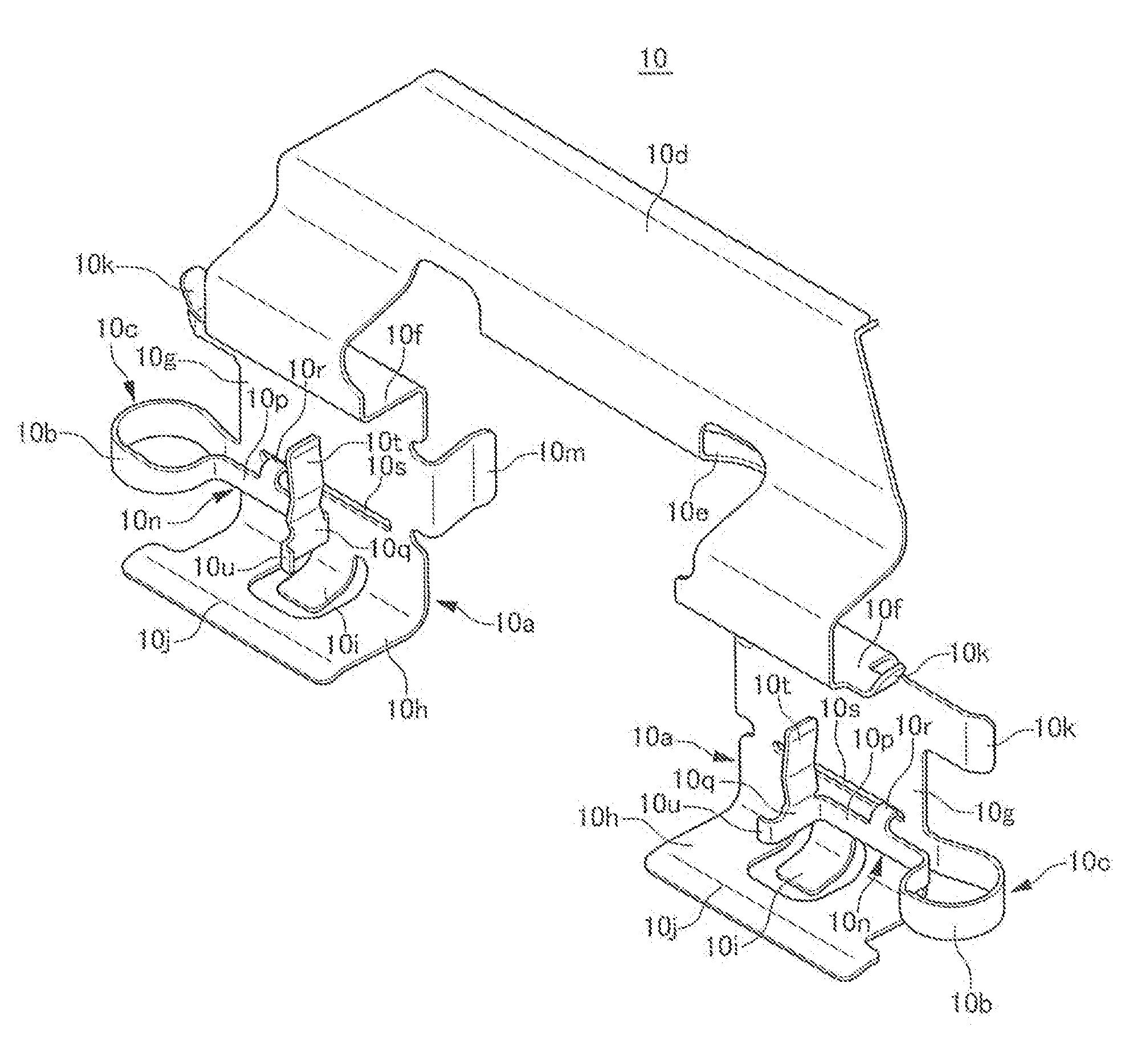
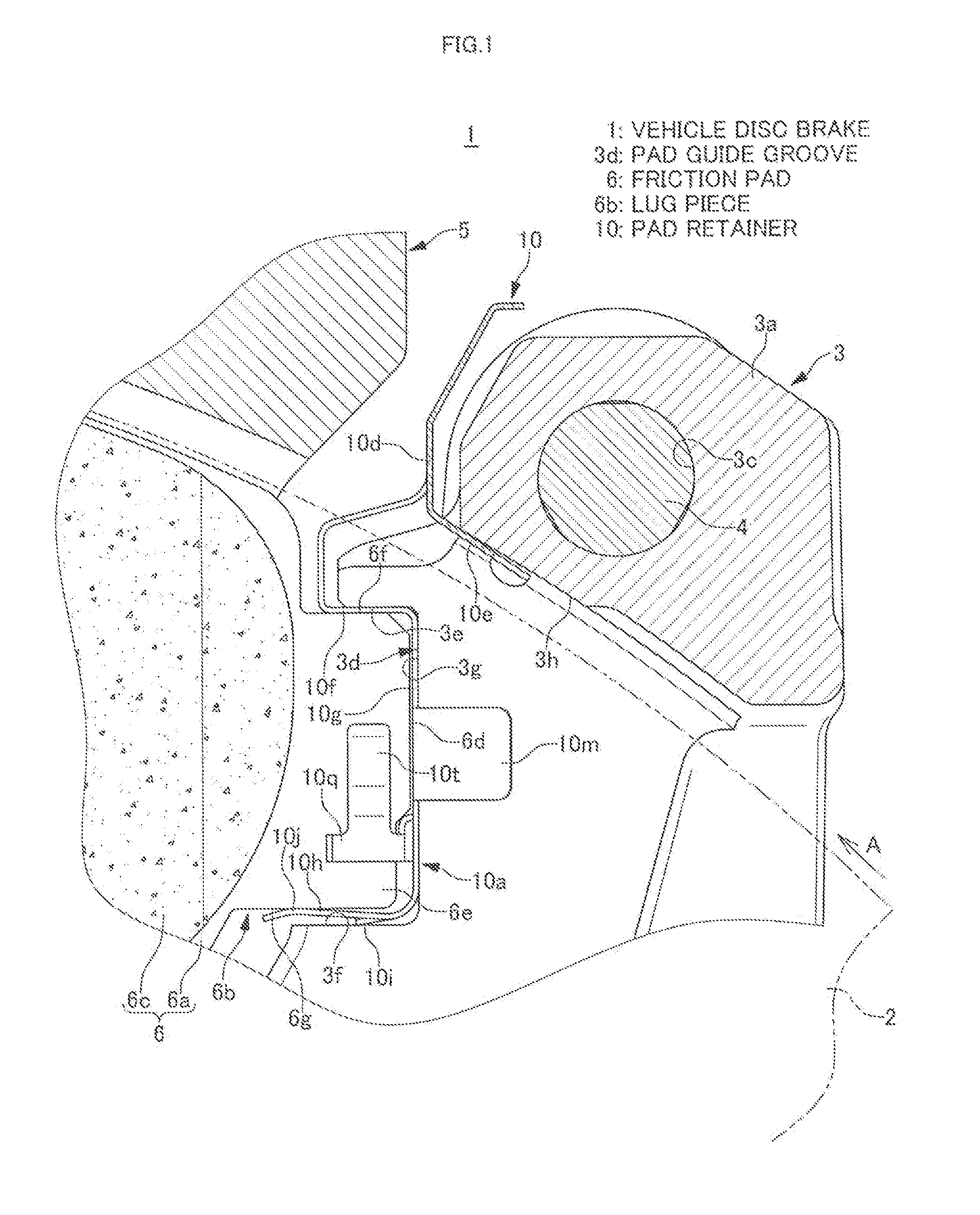
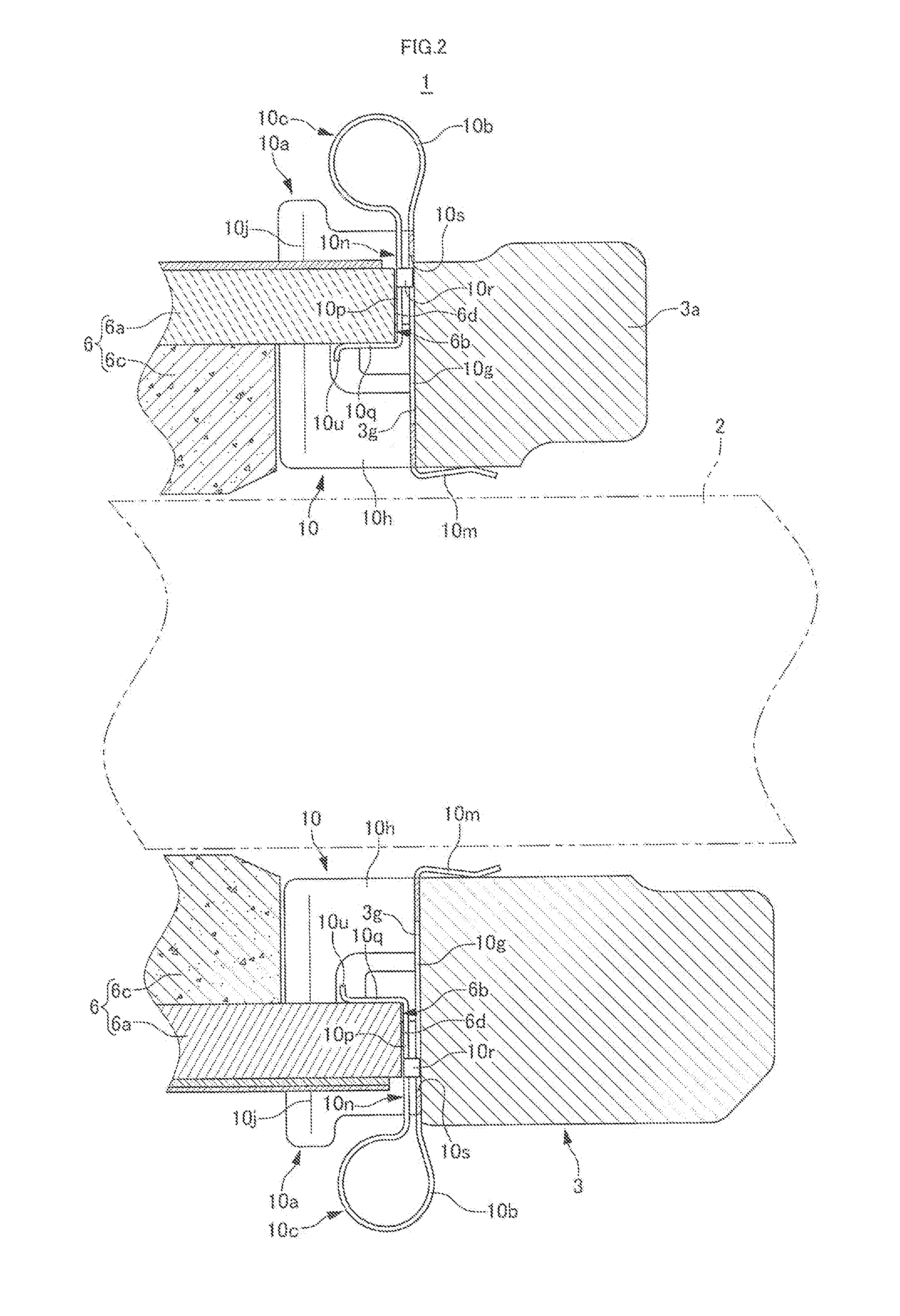
[0022]FIGS. 1 to 10 are views for illustrating an embodiment of a vehicle disc brake of the present invention. An arrow A indicates a rotational direction of a disc rotor configured to rotate together with a front wheel when a vehicle travels forwards. A disc rotation outlet side and a disc rotation inlet side to be described later are those resulting when the vehicle travels forwards.

[0023]The vehicle disc brake 1 includes: a disc rotor 2 configured to rotate together with a wheel; a caliper bracket 3 fixedly provided on a vehicle body on one side portion of the disc rotor 2; a caliper body 5 configured to be supported movably in a disc axis direction via a pair of slide pins 4, 4 by caliper supporting arms 3a, 3a of the caliper bracket 3; and a pair of friction pads 6, 6 disposed to face each other and to sandwich the disc rotor 2 on inner sides of an acting portion 5a and a reacting portion 5b of the caliper body 5.

[0024]The caliper body 5 is made up of the acting portion 5a and ...


PUM


Abstract

A pad retainer of a vehicle disc brake includes: a pair of retainer portions mounted in pad guide grooves; a connecting piece connecting the pair of retainer portions together; and pad returning portions configured to bias the friction pads to a side opposite to the disc rotor. Each of the pad returning portions includes an elastic loop portion formed into an arc shape by bending a narrow elongated piece, which extends in a direction opposite to the disc rotor from an inner side in a disc radial direction of a deep side piece of the retainer portion, and then back towards the disc rotor; and a holding portion extending from a bent-back end of the elastic loop portion towards the disc rotor and configured to hold a lug piece of the friction pad.

Description

BACKGROUND OF THE INVENTION[0001]1. Field of the Invention[0002]The present invention relates to a vehicle disc brake used for vehicles such as automobiles and motorcycles, and specifically relates to a structure of a pad retainer configured to movably support lug pieces provided at a shoe of a friction pad by pad guide grooves formed in caliper supporting arms.[0003]2. Description of the Related Art[0004]In a conventional vehicle disc brake including lug pieces which are respectively projecting from both side portions of a shoe of a friction pad, the lug pieces are movably supported in pad guide grooves formed in caliper supporting arms of a caliper bracket, so that the friction pads are hung movably in a disc axis direction. In addition, a pad retainer formed of a thin metallic plate is interposed between the pad guide groove and the lug piece. The pad retainer is configured to guide a movement of the friction pad in the disc axis direction, and to return the friction pad from a s...

Claims


Application Information

Patent Timeline
Patent Type & Authority Patents(United States)
IPC IPC(8): F16D65/40F16D55/00F16D65/00F16D65/02F16D65/097
CPCF16D65/0977F16D65/0006F16D65/02
Inventor MIURA, YASUTAKA
Owner HITACHI ASTEMO LTD
Why Eureka
Try Eureka