Electric wire holding structure and electric wire holding method

a technology of electric wire and holding structure, which is applied in the direction of insulated conductors, cables, conductors, etc., can solve the problems of complicated works and require complicated works, and achieve the effect of preventing deterioration of the bonding strength of a plurality, preventing deterioration of the bonding strength of the bonding part in the lateral direction, and reducing the number of work

Active Publication Date: 2016-03-08
YAZAKI CORP +1
View PDF20 Cites 1 Cited by
  • Summary
  • Abstract
  • Description
  • Claims
  • Application Information

AI Technical Summary

Benefits of technology

[0013]This invention has been made in view of the above described circumstances, and it is an object of the invention to provide an electric wire holding structure and an electric wire holding method in which deterioration of bonding strength between a plurality of electric wires can be prevented, without requiring complicated welding and bonding works.
[0020]The electric wire holding structure according to the invention includes a plurality of electric wires each having a rectangular conductive part which is formed at an end thereof, as a conductive part having a rectangular outer shape in a section perpendicular to an extending direction of the electric wires, wherein the rectangular conductive parts of the respective electric wires are bonded together by welding with ultrasonic vibration, and the rectangular conductive parts of a plurality of the electric wires are piled in a brick laying manner to be bonded together by welding. Therefore, an upper face or a bottom face of the rectangular conductive part which forms a bonding part in a vertical direction is arranged across a bonding part in a lateral direction. In case where the ultrasonic vibration in the vibrating direction which is parallel to side faces of the rectangular conductive part is applied, bonding strength of the bonding part in the lateral direction can be reinforced by the bonding part in the vertical direction where the bonding strength is unlikely to be deteriorated. As the results, it is possible to prevent deterioration of the bonding strength of a plurality of the electric wires, without making the welding and bonding work complicated.
[0021]In the electric wire holding method according to the invention, the rectangular conductive parts are formed in the respective ends of a plurality of the electric wires, as the conductive parts having a rectangular outer shape in the section perpendicular to the extending direction of the electric wires, and the rectangular conductive parts of a plurality of the electric wires are bonded together by welding with the ultrasonic vibration, and the electric wire holding method includes the piling step for piling the rectangular conductive parts of a plurality of the electric wires in the brick laying manner, and the welding and bonding step for applying the ultrasonic vibration to the rectangular conductive parts which have been piled in the brick laying manner thereby to bond the rectangular conductive parts together by -welding. Therefore, an upper face or a bottom face of the rectangular conductive part which forms a bonding part in a vertical direction is arranged across a bonding part in a lateral direction. In case where the ultrasonic vibration in the vibrating direction which is parallel to side faces of the rectangular conductive part is applied, bonding strength of the bonding part in the lateral direction can be reinforced by the bonding part in the vertical direction. As the results, it is possible to prevent deterioration of the bonding strength of a plurality of the electric wires, without making the welding and bonding work complicated.

Problems solved by technology

However, in the above described electric wire holding method, welding treatments must be repeatedly conducted, and there has been such a problem that complicated works are required.

Method used


Image

  • Electric wire holding structure and electric wire holding method
  • Electric wire holding structure and electric wire holding method
  • Electric wire holding structure and electric wire holding method

Examples


embodiment

(Embodiment)

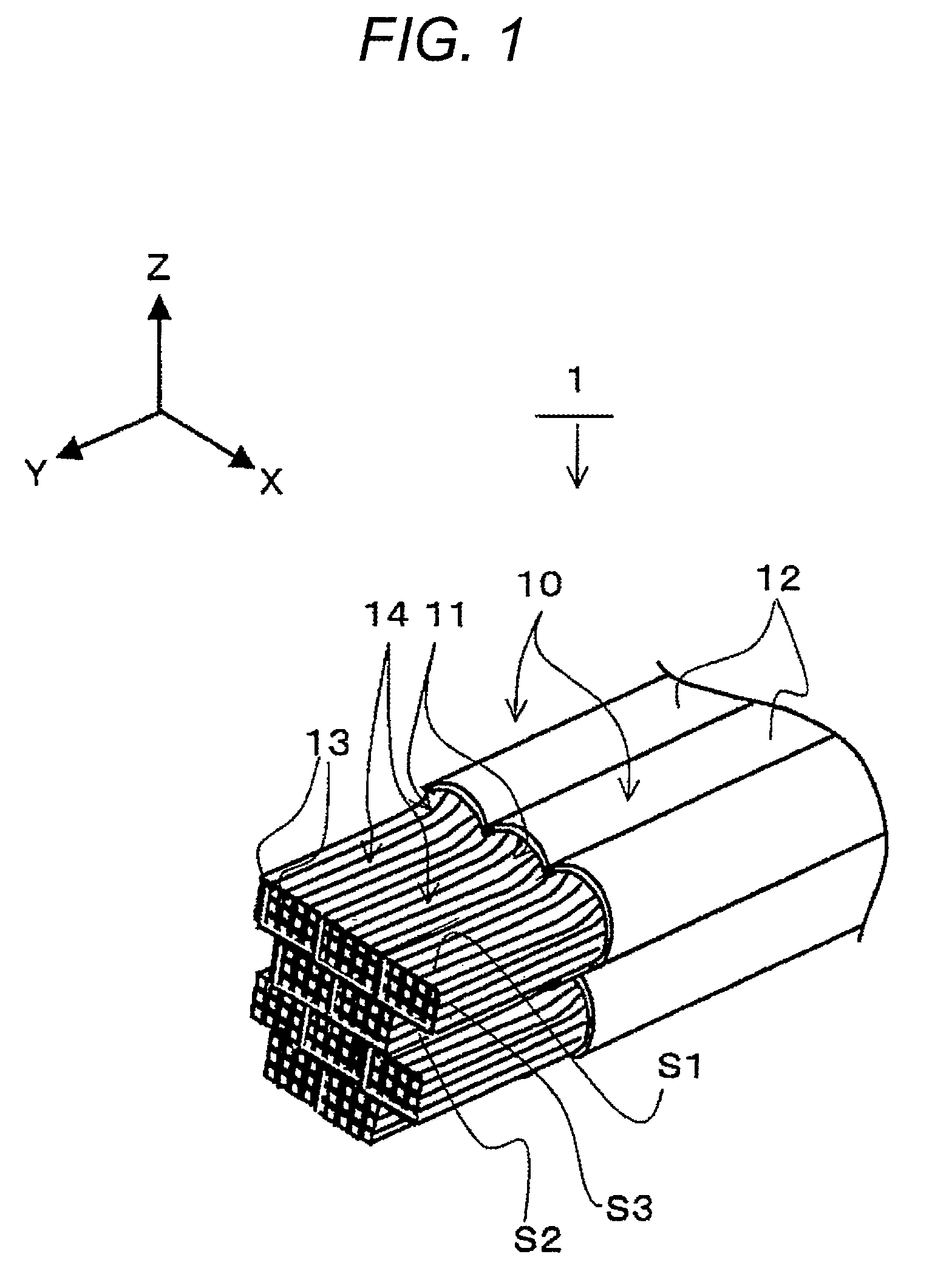
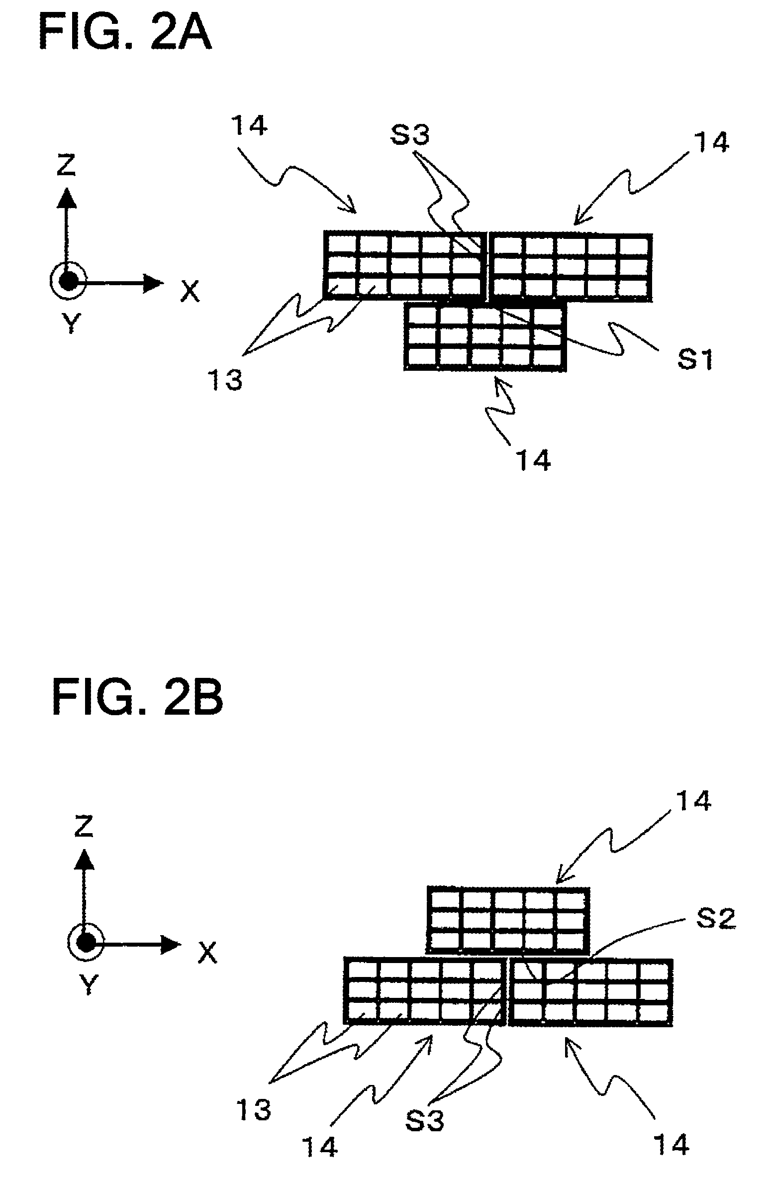
[0029]FIG. 1 is a perspective view showing an electric wire holding structure 1 in an embodiment according to the invention. FIGS. 2A and 2B are enlarged views of an essential part of the electric wire holding structure 1 as shown in FIG. 1. The electric wire holding structure 1 includes ten pieces of electric wires 10 which are superposed on one another and bonded together by welding, as shown in FIG. 1. Each of the electric wires 10 has a conductive part 11, and an insulating part 12 which covers the conductive part 11 for insulation and protection. It is to be noted that an arrow mark Y in the drawings represents an extending direction of the electric wire 10. Moreover, an arrow mark X represents a direction perpendicular to the arrow mark Y. Further, an arrow mark Z represents a direction perpendicular to a plane formed of the directions of the arrow marks X and Y.

[0030]The conductive part 11 is a bundle composed of a plurality of core wires 13 which are formed of co...

modification 1

(Modification 1)

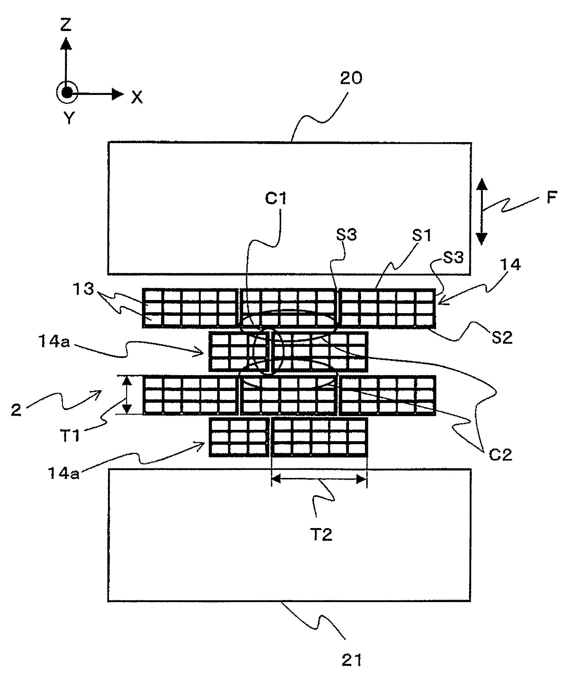
[0045]Then, Modification 1 of the embodiment according to the invention will be described. FIG. 5 is a view showing Modification 1 of the electric wire holding structure 1 in the embodiment according to the invention. In the electric wire holding structure 1 in the embodiment according to the invention, the rectangular conductive parts 14 of a plurality of the electric wires 10 which have been compressed so as to have the same size are exemplified. However, it would be sufficient that the rectangular conductive parts have a same thickness T1 in the piling direction (the Z direction). For this reason, in an electric wire holding structure 2 in Modification 1, rectangular conductive parts 14a which have a different thickness T2 in a direction perpendicular to the piling direction are mixed, as shown in FIG. 5, and the rectangular conductive parts 14 and 14a are piled in the brick laying manner. Also in the electric wire holding structure 2 in Modification 1, the bondin...

modification 2

(Modification 2)

[0046]Then, Modification 2 of the embodiment according to the invention will be described. FIG. 6 is a view showing Modification 2 of the electric wire holding structure 1 in the embodiment according to the invention. In the embodiment according to the invention, a case where the direction of the shorter side of the section of the rectangular conductive part 14 is the piling direction (the Z direction) is exemplified. However, in an electric wire holding structure 3 in Modification 2, the direction of the longer side of the section of the rectangular conductive part 14 is set to be the piling direction, as shown in FIG. 6. Also in this electric wire holding structure 3 in Modification 2, the bonding part C2 in the vertical direction reinforces the bonding strength of the bonding part C1 in the lateral direction, and hence, substantially the same effects as in the embodiment according to the invention can be attained. In short, it is possible to prevent deterioration ...


PUM

PropertyMeasurementUnit
electricaaaaaaaaaa
conductiveaaaaaaaaaa
thicknessaaaaaaaaaa

Abstract

An electric wire holding structure includes a plurality of electric wires each including a conductive part provided with a plurality of core wires and an insulating part covering the conductive part. The conductive part includes a rectangular conductive part which is formed at an end of the conductive part to have a rectangular outer shape in a section perpendicular to an extending direction of the electric wires. The rectangular conductive parts of the respective electric wires are bonded together by welding with ultrasonic vibration. The rectangular conductive parts of a plurality of the electric wires are piled in a brick laying manner to be bonded by welding.

Description

CROSS REFERENCE TO RELATED APPLICATION[0001]This application is a continuation of PCT application No. PCT / JP2011 / 075647, which was filed on Nov. 1, 2011 based on Japanese Patent Applications No. 2010-244977 filed on Nov. 1, 2010, the contents of which are incorporated herein by reference.BACKGROUND OF THE INVENTION[0002]1. Technical Field[0003]The present invention relates to an electric wire holding structure and an electric wire holding method for holding a plurality of electric wires.[0004]2. Background Art[0005]Conventionally, there has been an electric wire holding structure including a plurality of electric wires each of which is provided, at an end thereof, with a conductive part having a rectangular outer shape in a section perpendicular to an extending direction of the electric wires, wherein a plurality of the electric wires are bonded together by welding the rectangular conductive parts of the respective electric wires with ultrasonic vibration. More specifically, this el...

Claims


Application Information

Patent Timeline
Patent Type & Authority Patents(United States)
IPC IPC(8): H01B7/00H01R4/02H01R43/02H01B13/00
CPCH01B7/0009H01B13/0023H01R4/021H01R4/029H01R43/0207Y10T29/49201
Inventor TERASAKA, YUTAKA
Owner YAZAKI CORP
Why Eureka
Try Eureka