

Honeycomb structure
a honeycomb structure and honeycomb technology, applied in the field of honeycomb structure, can solve the problems of low mechanical strength of honeycomb structure having such structural characteristics, uneven temperature distribution in honeycomb structure, and deterioration of bonding strength in bonded portion, so as to inhibit the deterioration of bonding strength of the bonding layer
- Summary
- Abstract
- Description
- Claims
- Application Information
AI Technical Summary
Benefits of technology
Problems solved by technology
Method used
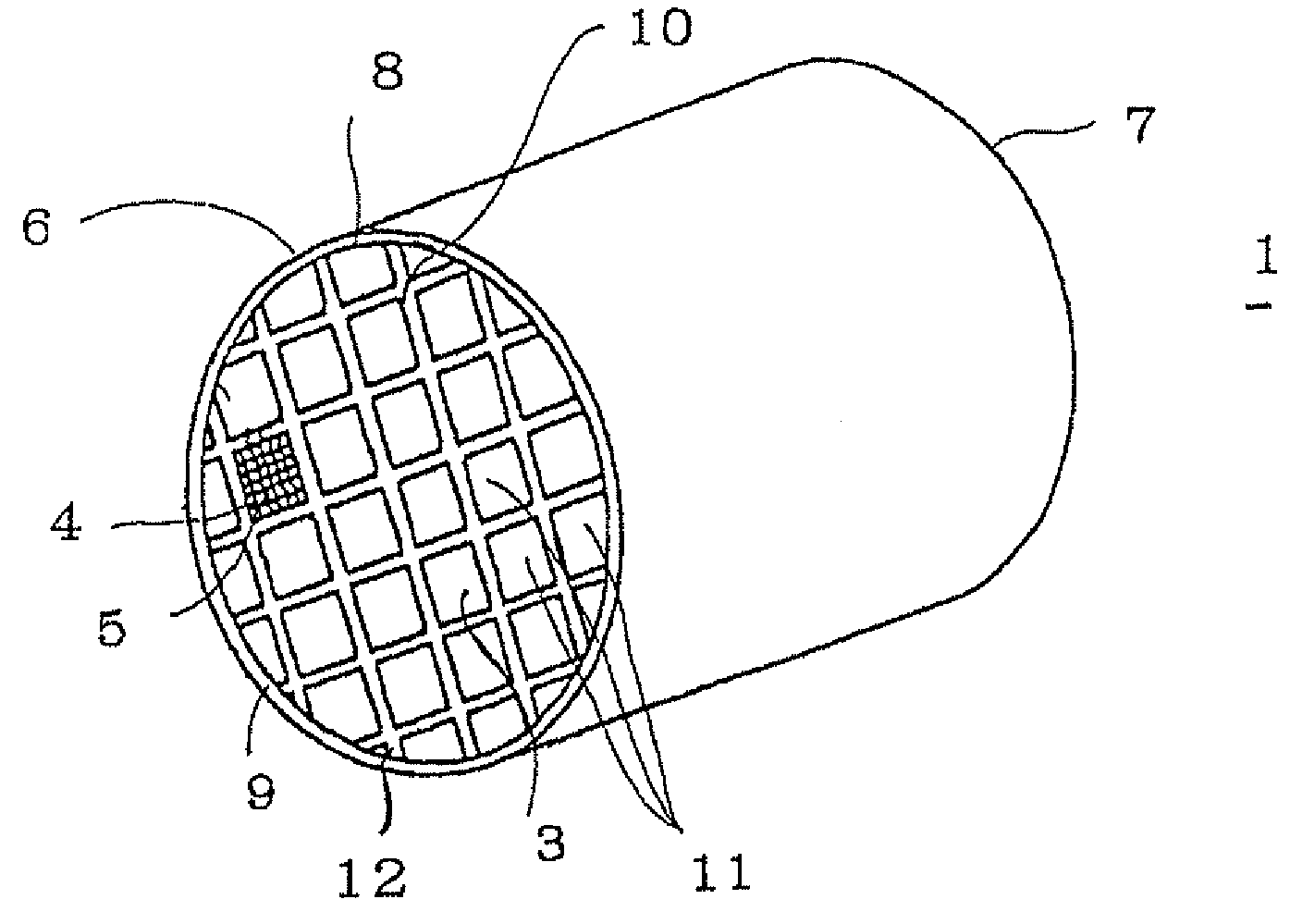
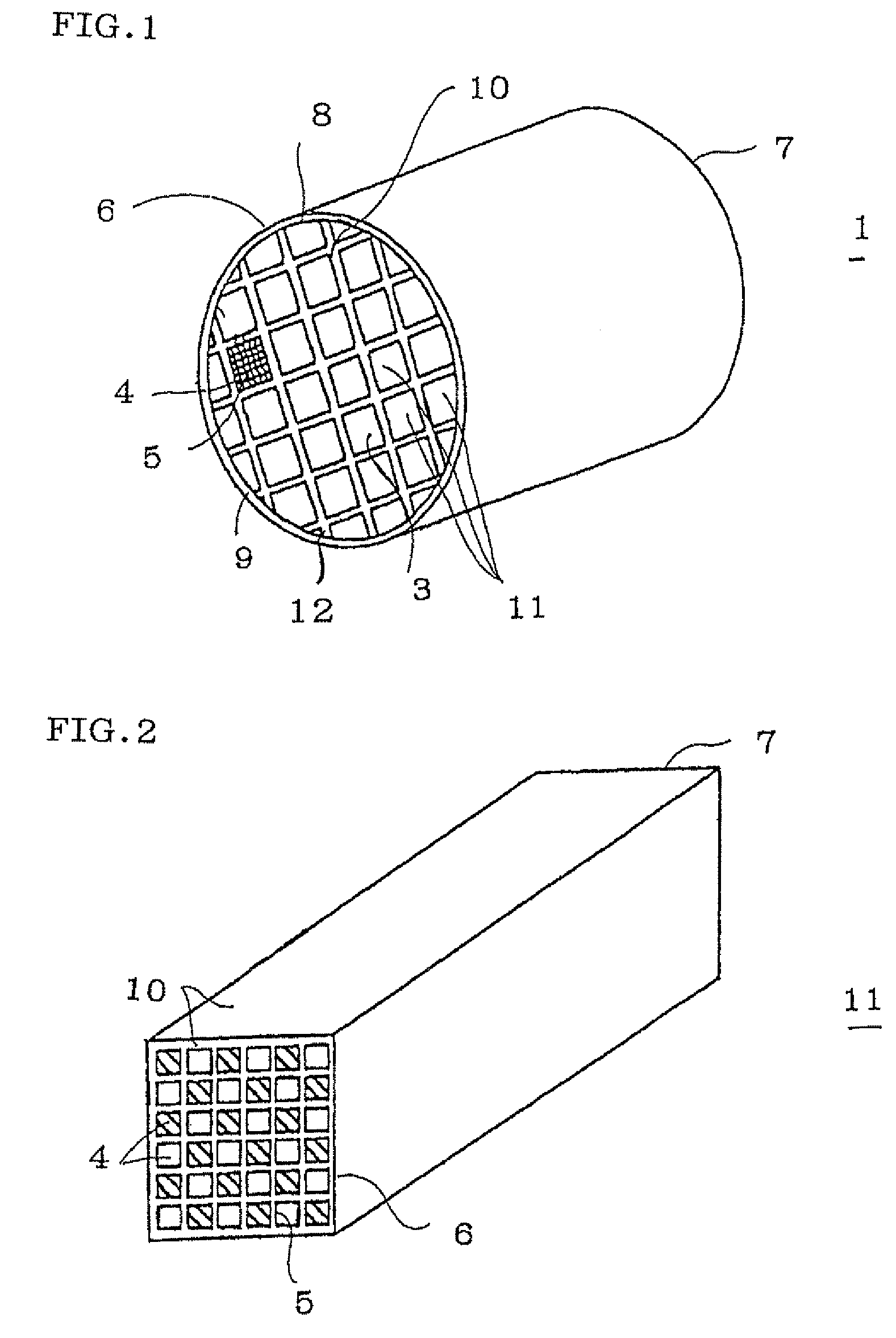
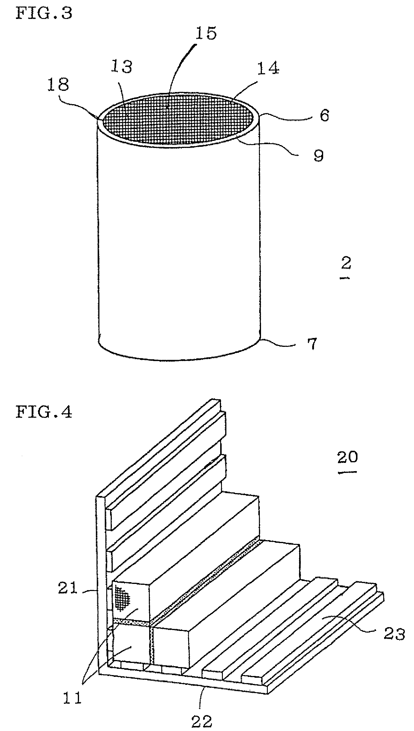
Image

Examples
example 1
[0150]There were employed 40% of a silicon carbide powder as the inorganic particle component, 28.5% of magnesium silicate fibers as the biologically soluble fibers, 30% of an aqueous solution of colloidal oxide having a silica solid content of 40%, 0.5% of carboxymethyl cellulose as the organic binder, and 1% of clay to obtain honeycomb-forming material (1). The honeycomb-forming material (1) was kneaded for 30 minutes with a mixer to prepare pasty honeycomb-forming slurry (1) (hereinbelow referred to as “slurry (1)”). The pH value of the slurry (1) right after the preparation was 6.0, the pH value when 24 hours passed after the preparation was 6.7, and the evaluation for the flowability was “good”.
example 2 to 6
[0151]The honeycomb-forming materials were obtained in the same manner as in Example 1 except for employing the compounds shown in Table 1 as the chelate compounds and adjusting additive amounts as shown in Table 1, and the honeycomb-forming slurry in each Example was obtained from each of the honeycomb-forming materials. The evaluation results of the slurry are shown in Table 1.
example 7
[0156]A mixture was obtained by the use of 40% of a silicon carbide powder as the inorganic particle component, 28.5% of magnesium silicate fibers as the biologically soluble fibers, 30% of an aqueous solution of colloidal oxide having 20% of a silica solid content (“FINE CATALOID C-127” (trade name) produced by JGC Catalysts and Chemicals Ltd.) as the inorganic binder, 0.5% of carboxymethyl cellulose as the organic binder, and 1% of clay. To the mixture was added 10% of the first buffer solution containing aminoacetic acid and hydrochloric acid as the additive to obtain the honeycomb-forming material (12). The honeycomb-forming material (12) was kneaded for 30 minutes with a mixer to obtain pasty honeycomb-forming slurry (12) (hereinbelow referred to as “slurry (12)”. The slurry (12) had a pH value of 3.6 right after the preparation and 3.7 after 24 hours from the preparation. The evaluation for flowability was “excellent”.
PUM
| Property | Measurement | Unit |
|---|---|---|
| porosity | aaaaa | aaaaa |
| pore diameter | aaaaa | aaaaa |
| thickness | aaaaa | aaaaa |
Abstract
Description
Claims
Application Information