
Honeycomb structure

a honeycomb structure and honeycomb technology, applied in the field of honeycomb structure, can solve the problems of low mechanical strength of honeycomb structure having such structural characteristics, uneven temperature distribution in honeycomb structure, and deterioration of bonding strength in bonded portion, so as to inhibit the deterioration of bonding strength of the bonding layer

Active Publication Date: 2010-01-07
NGK INSULATORS LTD
View PDF9 Cites 3 Cited by
  • Summary
  • Abstract
  • Description
  • Claims
  • Application Information

AI Technical Summary

Benefits of technology

The present invention provides two honeycomb structures that can prevent cracking and maintain strong bonding. The first structure includes a periphery-ground article and an outer peripheral coat layer formed by using honeycomb-forming slurry containing biologically soluble fibers and an inorganic binder. The second structure includes a periphery-ground article and an outer peripheral coat layer formed by using honeycomb-forming slurry containing biologically soluble fibers. These structures can prevent cracking and deterioration in bonding strength, even under high stress.

Problems solved by technology

However, in the case of regenerating a DPF by heating, temperature distribution in the honeycomb structure becomes uneven by rapid temperature change of exhaust gas or local heat generation, and there arises a problem of crack generation or the like.
In addition, a honeycomb structure having such structural characteristics generally has a problem of low mechanical strength because of thin partition walls and high porosity.
When a honeycomb structure is manufactured by the use of such a bonding material or an outer peripheral coat material having changed characteristics, bonding strength in a bonded portion may be deteriorated, or a crack may be generated in the outer peripheral coat layer.

Method used


Image

  • Honeycomb structure
  • Honeycomb structure
  • Honeycomb structure

Examples


example 1

[0130]There were employed 28.5% of magnesium silicate fibers as the biologically soluble fibers, 30% of an aqueous solution of colloidal oxide having a pH value of 9.2 and a silica solid content of 10%, which was adjusted by the use of and a modified silica sol obtained by adding an aqueous solution of a water-soluble metalate of an amphoteric metal to silica sol, as the inorganic binder, 40% of a silicon carbide powder as the inorganic particle component, 0.5% of carboxymethyl cellulose as the organic binder, and 1% of clay to obtain honeycomb-forming material (1). The honeycomb-forming material (1) was kneaded for 30 minutes with a mixer to prepare pasty honeycomb-forming slurry (1) (hereinbelow referred to as “slurry (1)”). The pH value of the slurry (1) right after the preparation was 9.5, the pH value when 24 hours passed after the preparation was 9.7, and the evaluation for the flowability was “excellent”. Incidentally, the average particle diameter of the silica solid content...

example 2

[0131]The honeycomb-forming material (2) was obtained in the same manner as in Example 1 except for employing an aqueous solution of a colloidal oxide having a pH value of 10.0 as the inorganic binder and employing a modified silica sol manufactured by adding a substance containing amine to prepare pasty honeycomb-forming slurry (2) (hereinbelow referred to as “slurry (2) ”). The evaluation results of the slurry (2) are shown in Table 1. Incidentally, the average particle diameter of the silica solid content was 37 nm.

example 3

[0132]The honeycomb-forming material (3) was obtained in the same manner as in Example 1 except for employing an aqueous solution of a colloidal oxide having a pH value of 9.4 as the inorganic binder to prepare pasty honeycomb-forming slurry (3) (hereinbelow referred to as “slurry (3) ”). The evaluation results of the slurry (3) are shown in Table 1. Incidentally, the average particle diameter of the silica solid content was 52 nm.


PUM

PropertyMeasurementUnit
particle diameteraaaaaaaaaa
porosityaaaaaaaaaa
pore diameteraaaaaaaaaa

Abstract

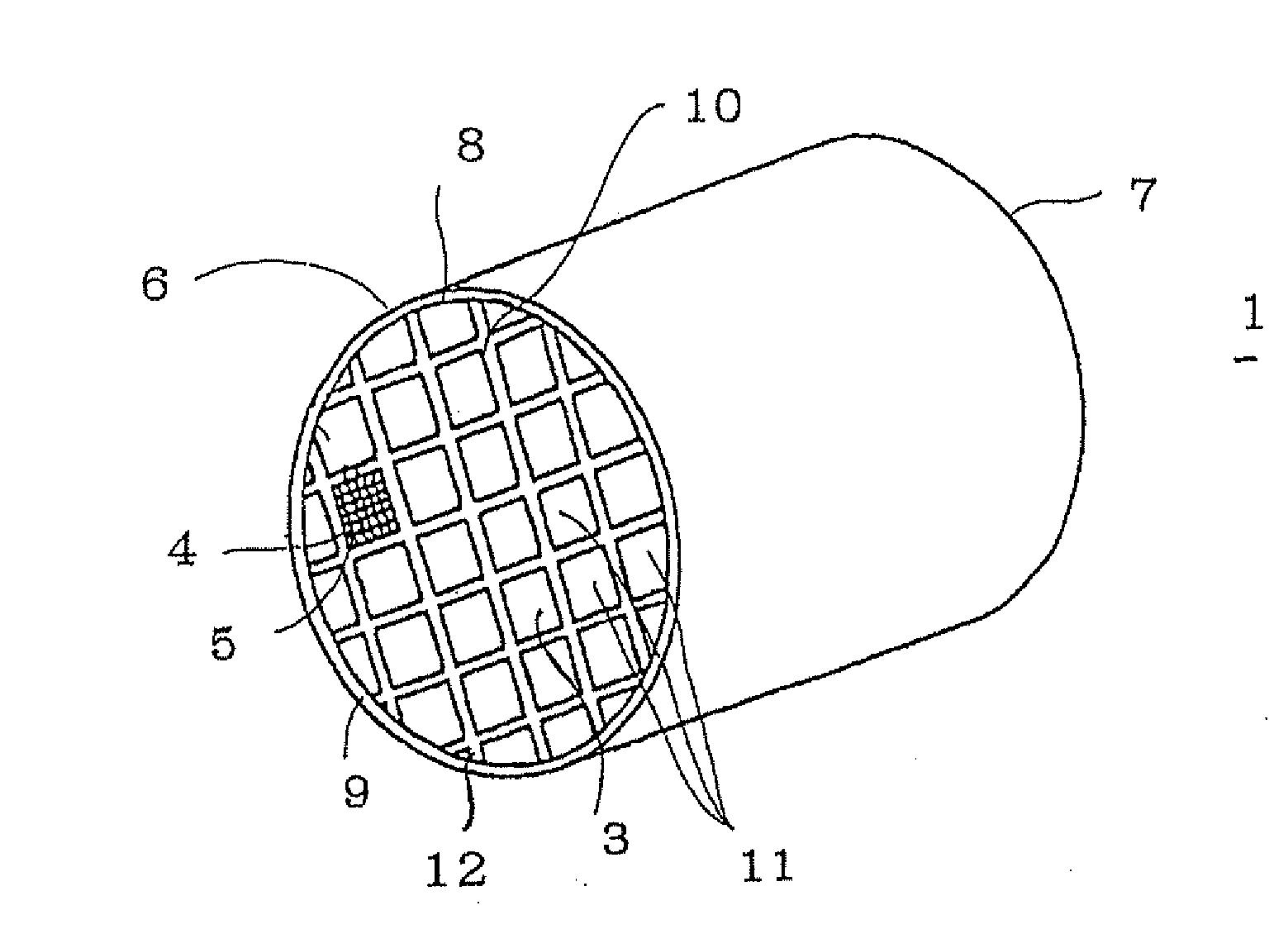
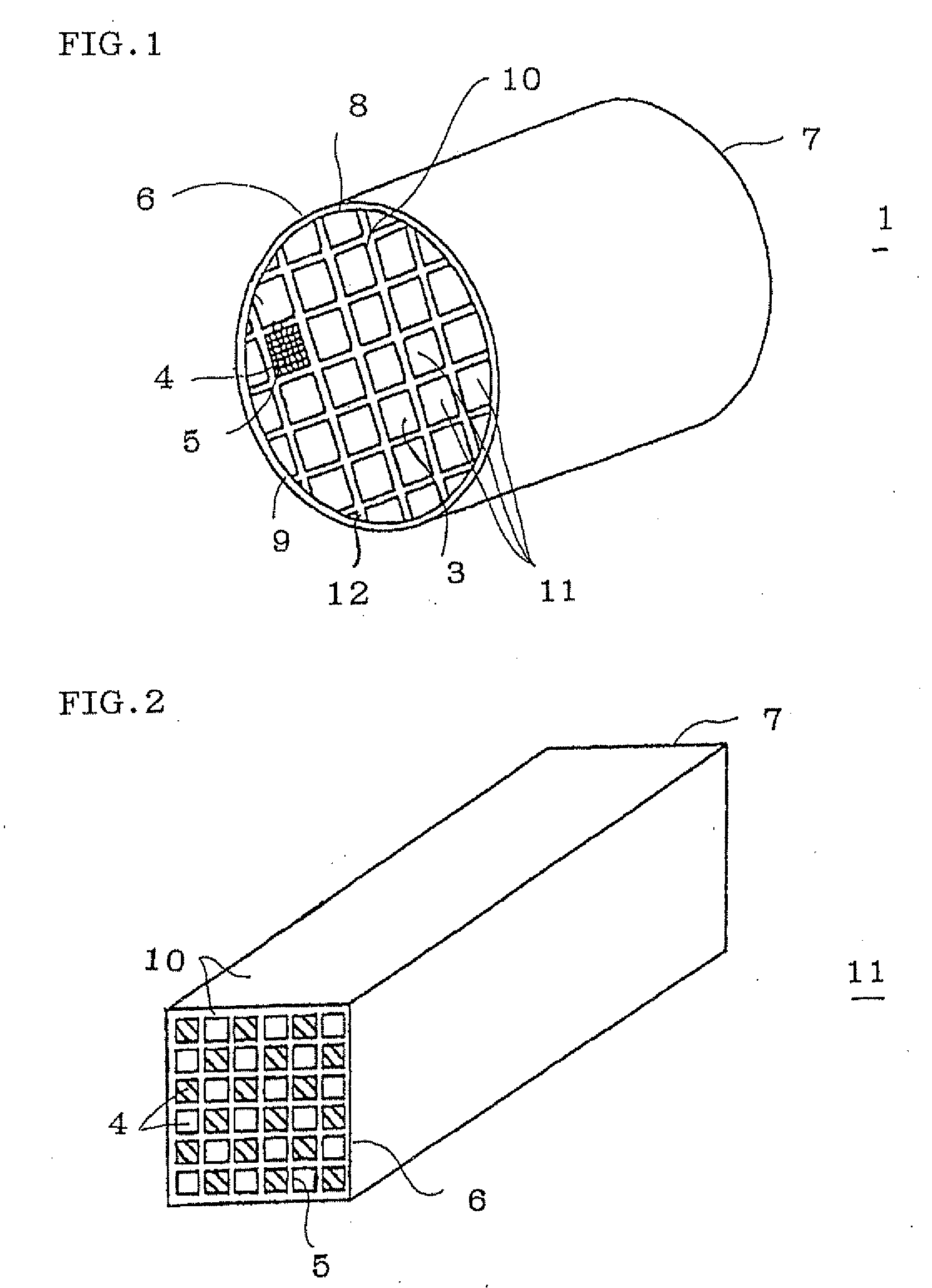
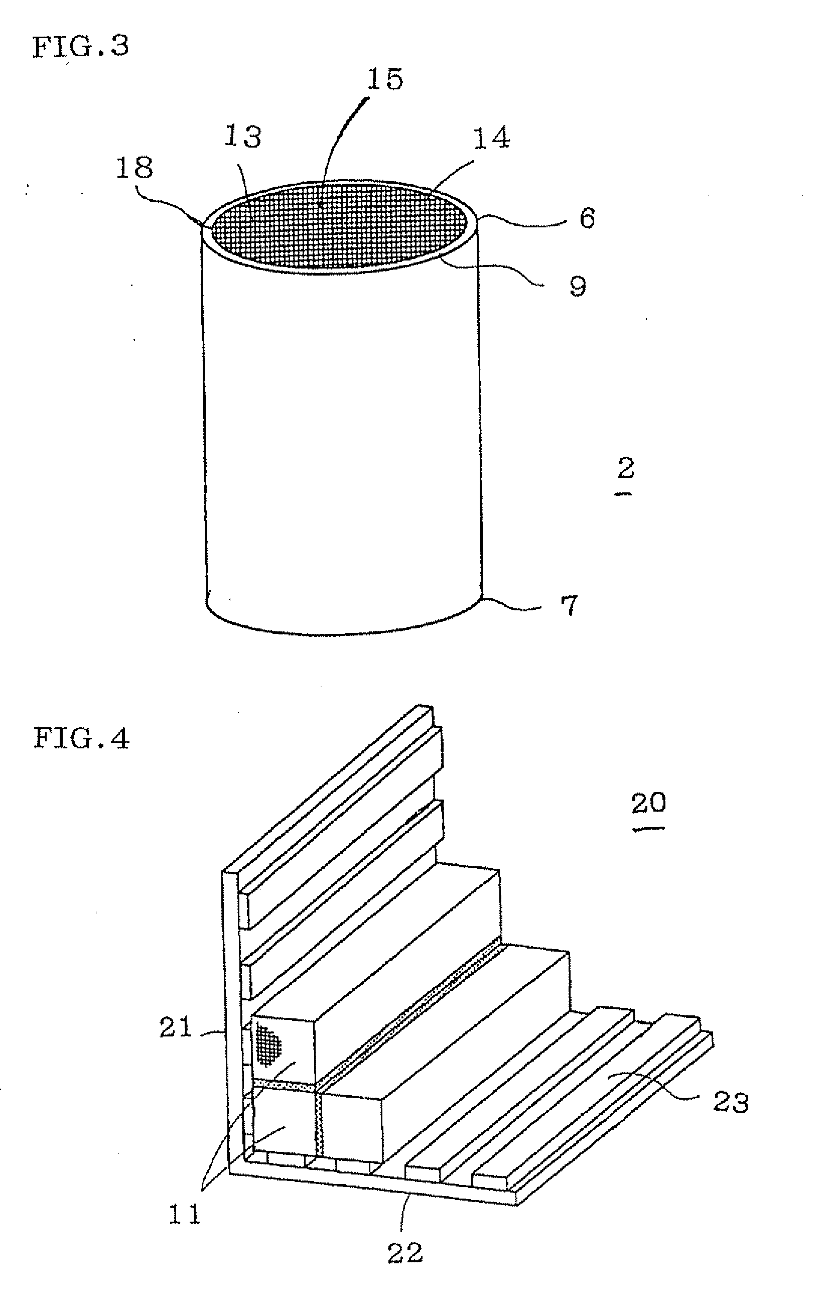
A honeycomb structure includes: a periphery-ground article obtained by grinding an outer peripheral portion of a cell structure 3 where honeycomb segments 11 are bonded by a bonding layer 12 at an outer wall 10 of each of them, and an outer peripheral coat layer 9 disposed on an outer peripheral face 8 of the periphery-ground article; wherein at least one of the bonding layer 12 and the outer peripheral coat layer 9 is formed using honeycomb-forming slurry containing biologically soluble fibers containing a metal oxide capable of extricating a metal ion and an inorganic binder containing a colloidal oxide having modified silica sol manufactured by adding a substance containing amine or an aqueous solution of a water-soluble metalate of an amphoteric metal to silica sol. Crack generation of the outer peripheral coat layer and / or deterioration of bonding strength of the bonding layer can be inhibited.

Description

BACKGROUND OF THE INVENTION AND RELATED ART [0001]The present invention relates to a honeycomb structure. More specifically, the present invention relates to a honeycomb structure capable of inhibiting crack generation of the outer peripheral coat layer and / or deterioration in bonding strength of the bonding layer containing biologically soluble fibers can be inhibited, and a honeycomb structure capable of inhibiting crack generation of the outer peripheral coat layer.[0002]In order to trap particulate matter such as dust contained in automobile exhaust gas or incineration exhaust gas generating upon incineration of waste, a honeycomb filter of a ceramic honeycomb structure is used. In particular, in order to efficiently remove particulate matter (hereinbelow sometimes referred to as “PM”) such as soot discharged from an internal combustion engine, a diesel particulate filter (hereinbelow sometimes referred to as a “DPF”) is used.[0003]In the DPF, since clogging is finally caused if...

Claims


Application Information

Patent Timeline
Patent Type & Authority Applications(United States)
IPC IPC(8): B32B3/12
CPCB01J35/04Y10T428/24149C01B33/146C04B12/04C04B28/24C04B35/565C04B35/6316C04B35/632C04B37/005C04B38/0019C04B41/009C04B41/5059C04B41/87C04B2111/00793C04B2235/3418C04B2235/349C04B2235/5228C04B2235/5436C04B2235/5454C04B2237/083C04B2237/34C04B2237/365C04B2237/38F01N3/0222B82Y30/00C04B14/4643C04B41/4539C04B41/5089C04B14/10C04B14/324C04B24/383C04B35/195C04B35/185C04B35/584C04B38/0006B01J35/56
Inventor SATO, FUMIHARUHIRAMATSU, TAKUYAICHIKAWA, SHUICHI
Owner NGK INSULATORS LTD
Learn More