Corner clamp and method for providing a suspension point in a three-dimensional space

a three-dimensional space and corner clamp technology, applied in the field of corner clamps and methods for hanging articles in space, can solve the problems of associated damage, the need to drill into the wall remains, and the damage to the wall remains, so as to improve the effect of the corner clamp

Inactive Publication Date: 2016-03-15
VAN MAASAKKERS WILHELMUS HENRICUS ALBERTUS
View PDF21 Cites 0 Cited by
  • Summary
  • Abstract
  • Description
  • Claims
  • Application Information

AI Technical Summary

Benefits of technology

[0006]It is an object of the present inve

Problems solved by technology

If the painting must be moved or removed, damage to the wall remains.
The necessity of drilling into the wall remains however, with the associated dama

Method used


Image

  • Corner clamp and method for providing a suspension point in a three-dimensional space
  • Corner clamp and method for providing a suspension point in a three-dimensional space
  • Corner clamp and method for providing a suspension point in a three-dimensional space

Examples


Embodiment Construction

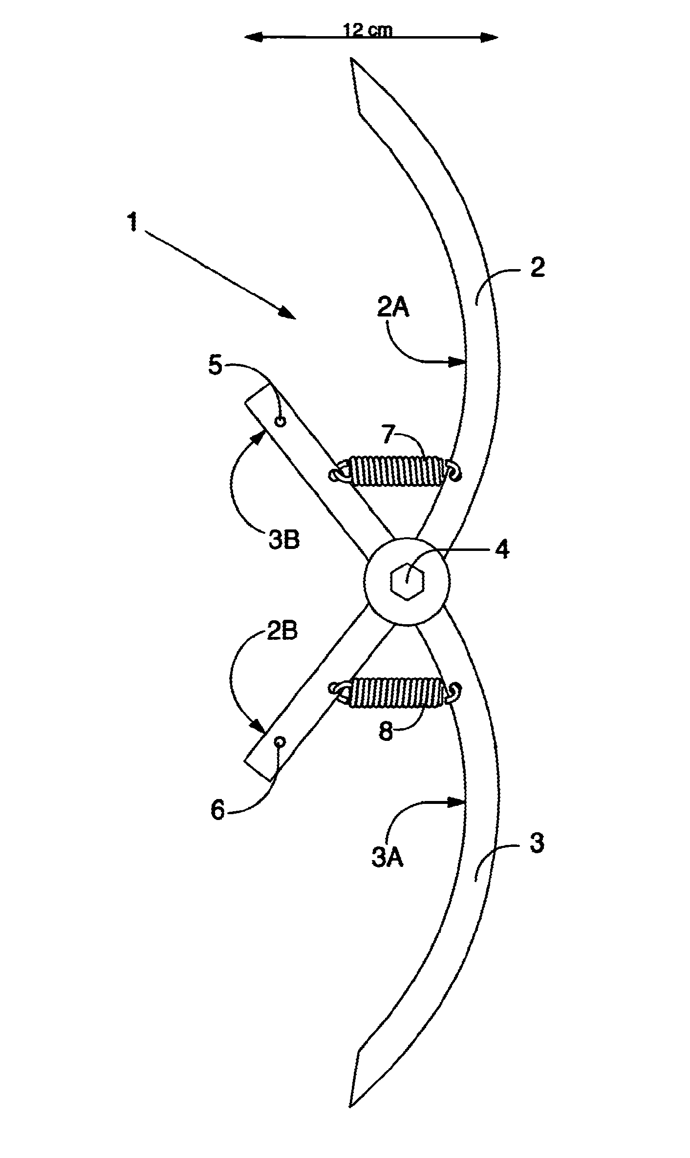
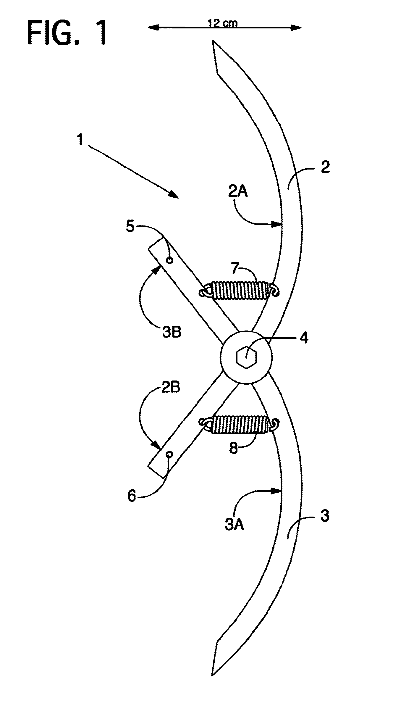
[0049]FIG. 1 shows schematically a corner clamp 1 according to an embodiment of the invention. Corner clamp 1 comprises two elongate rigid elements 2,3 which are connected pivotally to each other at a pivot point 4. The word rigid is understood to mean that elements 2,3 are not flexible, at least not as a result of forces which occur during normal use. In the example of FIG. 1 elements 2,3 are connected via a metal bolt, although the skilled person will appreciate that many other options are possible. In this embodiment elements 2,3 consist of curved metal flat rods 2,3. Other forms and materials are possible. Element 2 has two arms 2A,2B and element 3 has two arms 3A,3B, see FIG. 1. Element 3 comprises a fastening member 5 which consists of a hole 5 arranged in flat metal rod 3. Also present in this embodiment is a second fastening member 6 which is arranged in arm 2B, see hole 6.

[0050]Corner clamp 1 further comprises two springs 7,8 which are arranged between elements 2,3 as shown...


PUM

PropertyMeasurementUnit
Lengthaaaaaaaaaa
Angleaaaaaaaaaa

Abstract

A corner clamp for clamping thereof between two surfaces substantially at right angles to each other includes a first rigid element having a first outer end for supporting, optionally via a contact member which can be fixed thereto, on a first of the two surfaces; a second rigid element having a second outer end for supporting, optionally via a contact member coupled thereto, on a second of the two surfaces. The second element is coupled pivotally to the first element at a pivot point. The corner clamp has one or more placing states in which the elements are positioned such that, when clamped in the corner, the pivot point is situated between the corner and a straight line running from the first outer end to the second outer end.

Description

BACKGROUND OF THE INVENTION[0001]1. Field of the Invention[0002]The present invention relates to a corner clamp and method for hanging articles in a space. The corner clamp can for instance be used to hang paintings against the wall.[0003]2. Description of the Related Art[0004]In order to hang an article such as a painting use is often made of hooks, nails or screws which are hammered or screwed into the wall. When screws are used a hole is first drilled, after which a plug is for instance inserted. If the painting must be moved or removed, damage to the wall remains. An alternative is to use a rail system wherein the paintings can be moved in simple manner. The necessity of drilling into the wall remains however, with the associated damage.[0005]Patent publication DE102006034343 A1 describes a corner clamp which in an embodiment comprises two rigid elements which are attached to each other at a pivot point. The clamp can be fixed in a corner between for instance a wall and a ceilin...

Claims


Application Information

Patent Timeline
IPC IPC(8): A47G1/10A47G1/16F16B2/18
CPCA47G1/1653F16B2/18Y10T29/49826
Inventor VAN, MAASAKKERS, WILHELMUS, HENRICUS, ALBERTUS
Owner VAN MAASAKKERS WILHELMUS HENRICUS ALBERTUS
Why Eureka
Try Eureka