High pressure control valve

a high-pressure control valve and valve body technology, applied in the direction of valve details, wear-reducing fuel injection, fuel injection apparatus, etc., can solve the problems of damage to the high-pressure pump of the fuel system, material ablation, and ultimately loss of the tightness of the valve in the area of the press fitting, etc., to achieve good sealing, lead especially easily, and actuate the sealing element. the effect of easy actuation

Active Publication Date: 2016-03-29
KENDRION VILLINGEN GMBH
View PDF23 Cites 0 Cited by
  • Summary
  • Abstract
  • Description
  • Claims
  • Application Information

AI Technical Summary

Benefits of technology

[0017]One of the proposed goals, but not a requirement, is to provide a high-pressure regulating valves to enable a use at higher pressures than the current 2700-3000 bar, while at the same time lessening the material erosion.
[0029]It is especially advantageous in terms of fluid mechanics when a flow cross section is formed between the actuating element and the projection so that flow turbulence is reduced. In this way, an especially regular fluid flow is achieved and forces induced in the fluid circulation by turbulence are reduced.

Problems solved by technology

An attenuation of the valve body 2 in this area implies serious drawbacks in regard to the lifetime of the valve, since with increasing erosion less force can be transmitted from the screw connection via the valve seat 3 to the valve body 2, so that the valve ultimately loses its tightness in the area of the press fitting.
A further drawback of erosion is the subsequent ablation of material.
Particles of the ablated material can get into the fuel system and thus, for example, lead to damaging of the high-pressure pump of the fuel system.

Method used


Image

  • High pressure control valve
  • High pressure control valve
  • High pressure control valve

Examples


Embodiment Construction

[0034]Reference will now be made in detail to several embodiments of the invention that are illustrated in the accompanying drawings. Wherever possible, same or similar reference numerals are used in the drawings and the description to refer to the same or like parts or steps. The drawings are in simplified form and are not to precise scale. For purposes of convenience and clarity only, directional terms, such as top, bottom, up, down, over, above, and below may be used with respect to the drawings. These and similar directional terms should not be construed to limit the scope of the invention in any manner. The words “connect,”“couple,” and similar terms with their inflectional morphemes do not necessarily denote direct and immediate connections, but also include connections through mediate elements or devices.

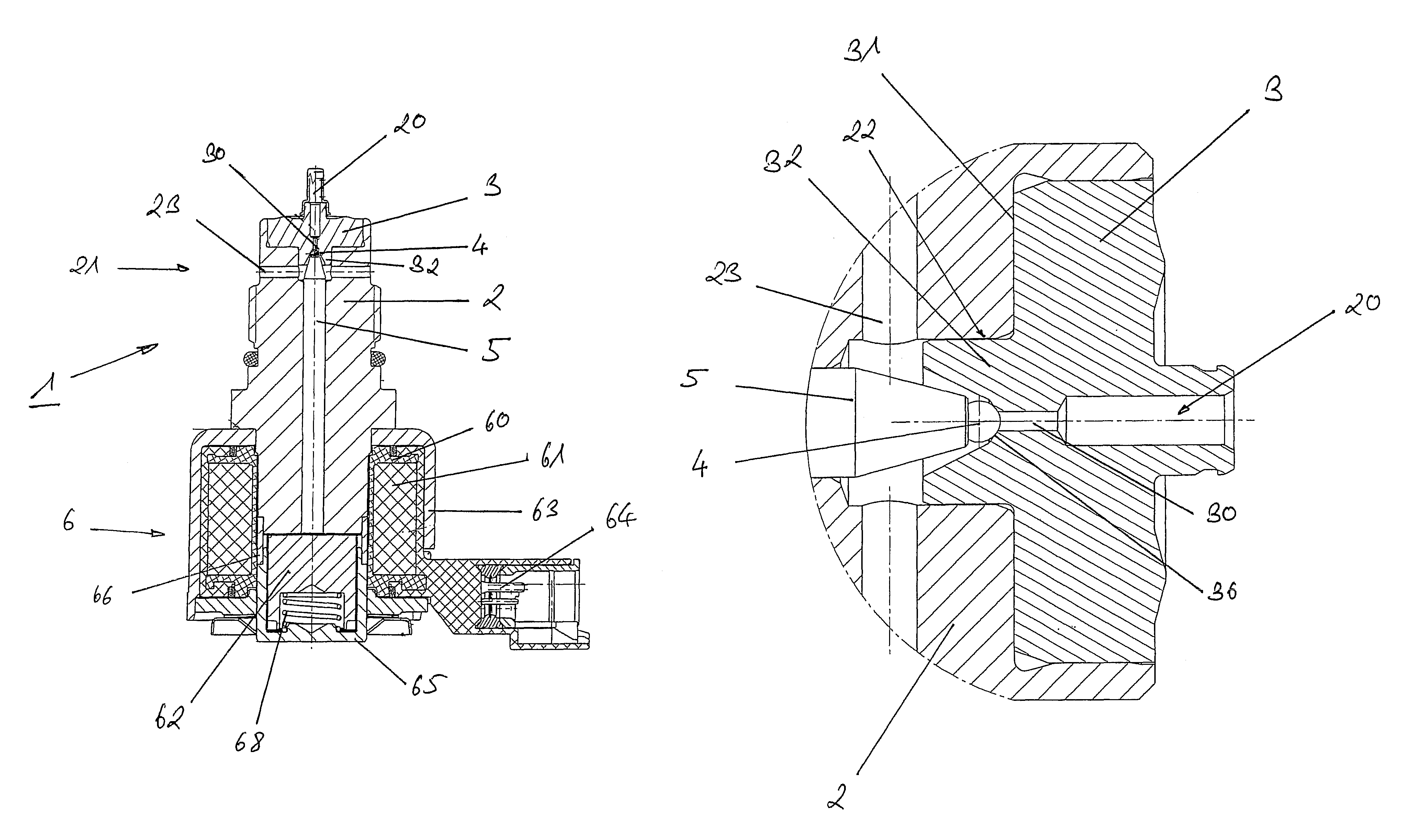
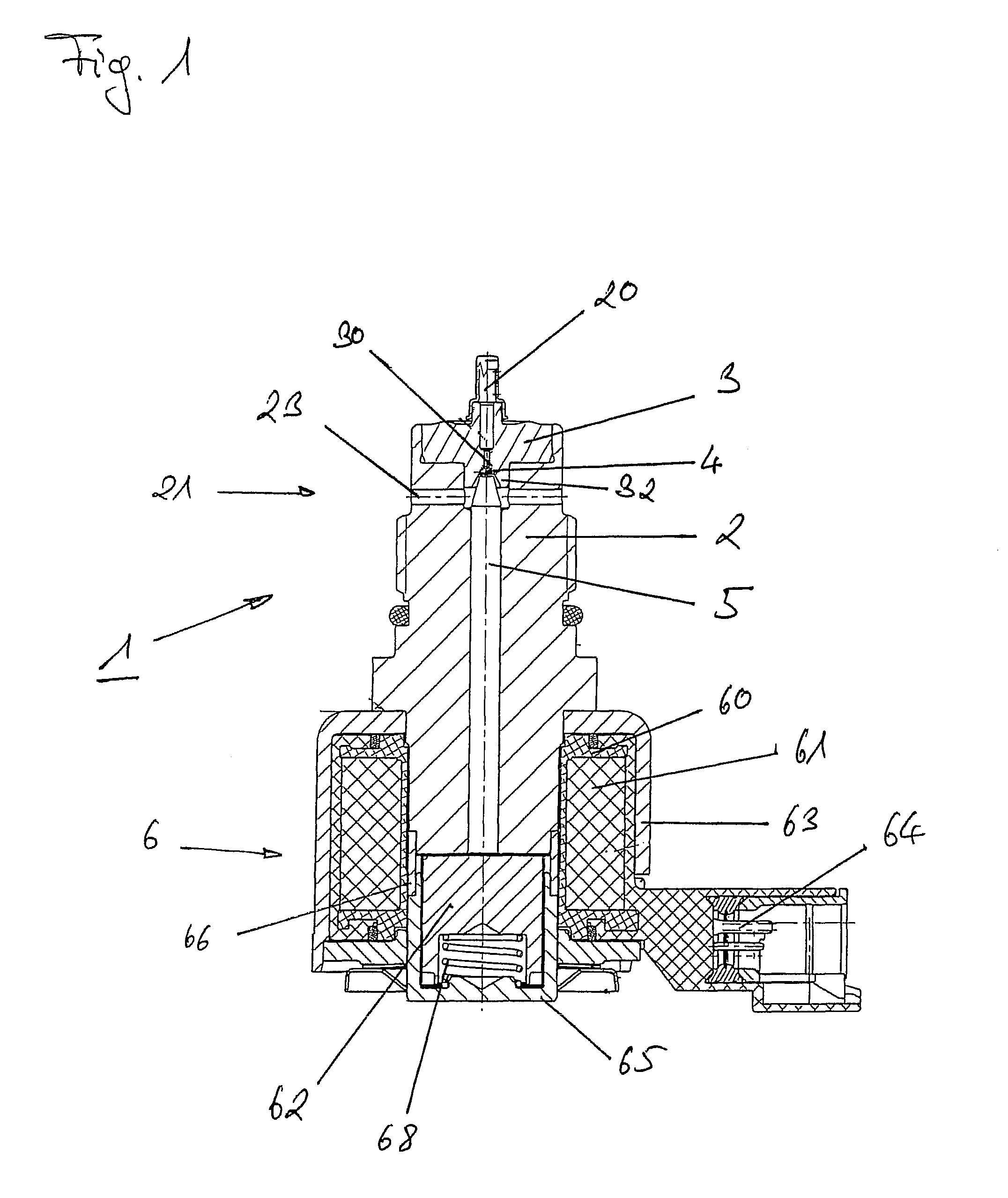
[0035]FIG. 1 shows a cross section through a high-pressure regulating valve 1 according to the invention. The high-pressure regulating valve 1 has an essentially cylindrical ...


PUM


Abstract

A high pressure control valve system with a valve body with an inlet and an outlet, whereby the outlet is shaped by at least one radially oriented opening in the valve body, an essentially discoidally shaped valve seat arranged on the valve body between inlet and outlet and features a valve body bore that connects inlet and outlet, a sealing element that is appropriately arranged on an actuating element in order to close the valve bore, and an actuating device suitably shaped to move the actuating element in such a way as to cause the opening and closing of the valve, characterized in that the valve seat on the exit site features a revolving extension, extending from a foot print axially in direction of the opening.

Description

CROSS REFERENCE TO RELATED APPLICATIONS[0001]This application claims priority from DE 10 2010 049 022.9 filed Oct. 21, 2010, the entire contents of which are incorporated herein by reference.FIGURE FOR PUBLICATION[0002]FIG. 2BACKGROUND OF THE INVENTION[0003]1. Field of the Invention[0004]The present invention relates to a high-pressure regulating valve. More particularly, the present invention relates to high-pressure regulating valve configured with a radially oriented opening in the valve body and improved performance.[0005]2. Description of the Related Art[0006]The high-pressure regulating of fluids occurs generally by means of ball-seat valves. These are as a rule electromagnetically actuated. Electromagnetically operated high-pressure regulating valves of the prior art are generally built as follows, an example is depicted in FIG. 3.[0007]The valve 1 has a valve body 2 with an inlet 20 and an outlet 21, in which pressures up to 2400 bar can occur at present at the inlet side or...

Claims


Application Information

Patent Timeline
Patent Type & Authority Patents(United States)
IPC IPC(8): F02M63/00F02M63/02F16K31/06
CPCF02M63/0077F02M63/005F02M63/0036F02M63/0052F02M63/025F16K31/0665F02M2200/02F02M2200/04Y10T137/7793
Inventor BURKART, HARALDMAIWALD, WOLFRAMYU, WEIZELANO, FRANKHEINGL, RALFGERHARDT, STEFANIE
Owner KENDRION VILLINGEN GMBH
Why Eureka
Try Eureka