Optical position measuring device
a technology of optical position measurement and measuring device, which is applied in the direction of measuring device, converting sensor output optically, instruments, etc., can solve the problems of inability to accurately measure the position of objects relative to the tcp, and inability to meet the typically high positioning specifications
- Summary
- Abstract
- Description
- Claims
- Application Information
AI Technical Summary
Benefits of technology
Problems solved by technology
Method used
Image
Examples
first exemplary embodiment
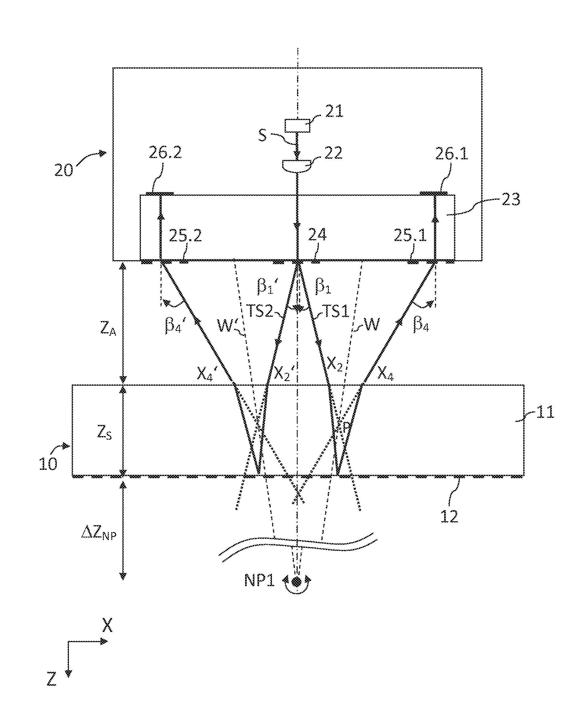
[0074]A first exemplary embodiment of the position measuring device is illustrated in various sectional views in FIGS. 3a to 3c. FIG. 3a illustrates the scanning beam path from light source 21 to reflectors 26.1, 26.2, and FIG. 3b correspondingly illustrates the scanning beam path from reflectors 26.1, 26.2 to detector elements 29.1 to 29.3 in an XZ view. FIG. 3c illustrates the entire scanning beam path in an YZ view.
[0075]The position measuring device includes a measuring standard 10 and at least one scanning head 20. Measuring standard 10 and scanning head 20 are movable relative to each other at least along the X axis, i.e., at least along one measuring direction, and, for example, are connected to movable components of a machine that must be positioned in relation to each other.
[0076]For example, this may be the XY table of a semiconductor production device, which is disposed so as to allow movement along the X and Y directions oriented perpendicularly to each other, i.e., alon...
second exemplary embodiment
[0085]A second exemplary embodiment of the optical position measuring device is illustrated in a cross-sectional view in FIG. 4. In the following text, only significant differences with respect to the previously described first exemplary embodiment are discussed.
[0086]Since the two partial bundles of rays in the first exemplary embodiment must pass through multiple gratings in the optical path, a reduction in the intensity of the partial bundles of rays may result and, accordingly, reduced signal strength. It is therefore advantageous to reduce the number of traversed gratings. One option in this regard is provided in the second exemplary embodiment. FIG. 4 illustrates only the optical path from light source 121 to reflectors 126.1, 126.2 of this example. The further optical path is identical with the optical path illustrated in FIG. 3b of the first exemplary embodiment. Also identical in this exemplary embodiment is the transverse view of the scanning optical path according to FIG....
third exemplary embodiment
[0093]A third exemplary embodiment of the optical position measuring device is illustrated in multiple cross-sectional views in FIGS. 5a to 5c, which correspond to the views of the first exemplary embodiment, i.e., FIG. 5a illustrates the optical path in the XZ projection from light source 221 to reflection grating 212 of measuring standard 210, FIG. 5b illustrates the further optical path illustrates up to detector elements 229.1 to 229.3, and FIG. 5c illustrates the transverse view of the optical path in the YZ projection. In the following text, it will once again be the case that only significant differences from the first exemplary embodiment are discussed.
[0094]In the present third exemplary embodiment of the optical position measuring device, the two partial bundles of rays TS1, TS2 are reflected only once at measuring standard 210. A bundle of rays emitted by light source 221 is collimated by a collimating optics system 222 and divided into two partial bundles of rays TS1, TS...
PUM
 Abstract
Description
Claims
Application Information
 - R&D
- Intellectual Property
- Life Sciences
- Materials
- Tech Scout
- Unparalleled Data Quality
- Higher Quality Content
- 60% Fewer Hallucinations
Browse by: Latest US Patents, China's latest patents, Technical Efficacy Thesaurus, Application Domain, Technology Topic, Popular Technical Reports.
© 2025 PatSnap. All rights reserved.Legal|Privacy policy|Modern Slavery Act Transparency Statement|Sitemap|About US| Contact US: help@patsnap.com


