Energy supply module and method of assembling the same

a technology of energy supply module and energy supply module, which is applied in the direction of machines/engines, applications, lighting and heating apparatus, etc., can solve the problems of requiring valuable space, requiring expensive and time-consuming processes, and requiring at least some known electrical generators

Active Publication Date: 2016-04-19
JUSTUS CHARLES ROBERT
View PDF59 Cites 18 Cited by
  • Summary
  • Abstract
  • Description
  • Claims
  • Application Information

AI Technical Summary

Problems solved by technology

For example, a generator may be used as a backup power source when a primary power source has failed or as a primary power source where traditional utility generated power is either unavailable or doesn't provide sufficient reliability or quantity.
Conventional generators used for such purposes are often of such size such that a standard-sized truck is only able to transport a single generator, or possibly a pair of generators, at any one time.
Moreover, such conventional generators typically require a crane to load and unload the generator from the truck and may require an additional mode of transportation to carry the other equipment associated with the generator, such as cabling and electrical connectors.
Therefore, the deployment of at least some known electrical generators may be an expensive and time consuming process.
However, in many cases, such as disaster relief efforts, users may also be in need of hot water for various uses.
A location having a generator that supplies electricity only would need to also include a hot water heater, which adds to expenses and requires valuable space to operate that may be better suited to other uses.
However, many generators require a number of additional electrical panels and cabling in order to break down the raw electric supplied from the generator to the circuits needed by the user.
Such restrictions may limit the positioning of the generator to less than ideal locations, or may require transporting additional cabling or an additional generator to the site, which increases the induced costs to a user.

Method used


Image

  • Energy supply module and method of assembling the same
  • Energy supply module and method of assembling the same
  • Energy supply module and method of assembling the same

Examples


Embodiment Construction

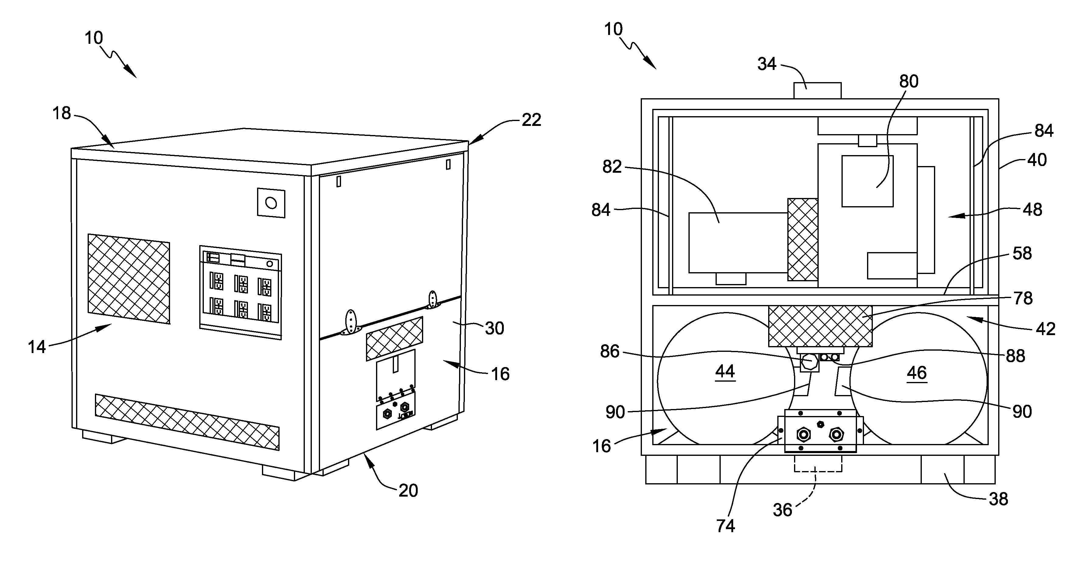
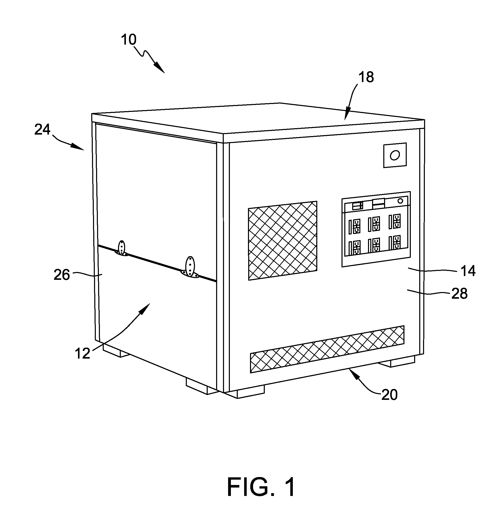
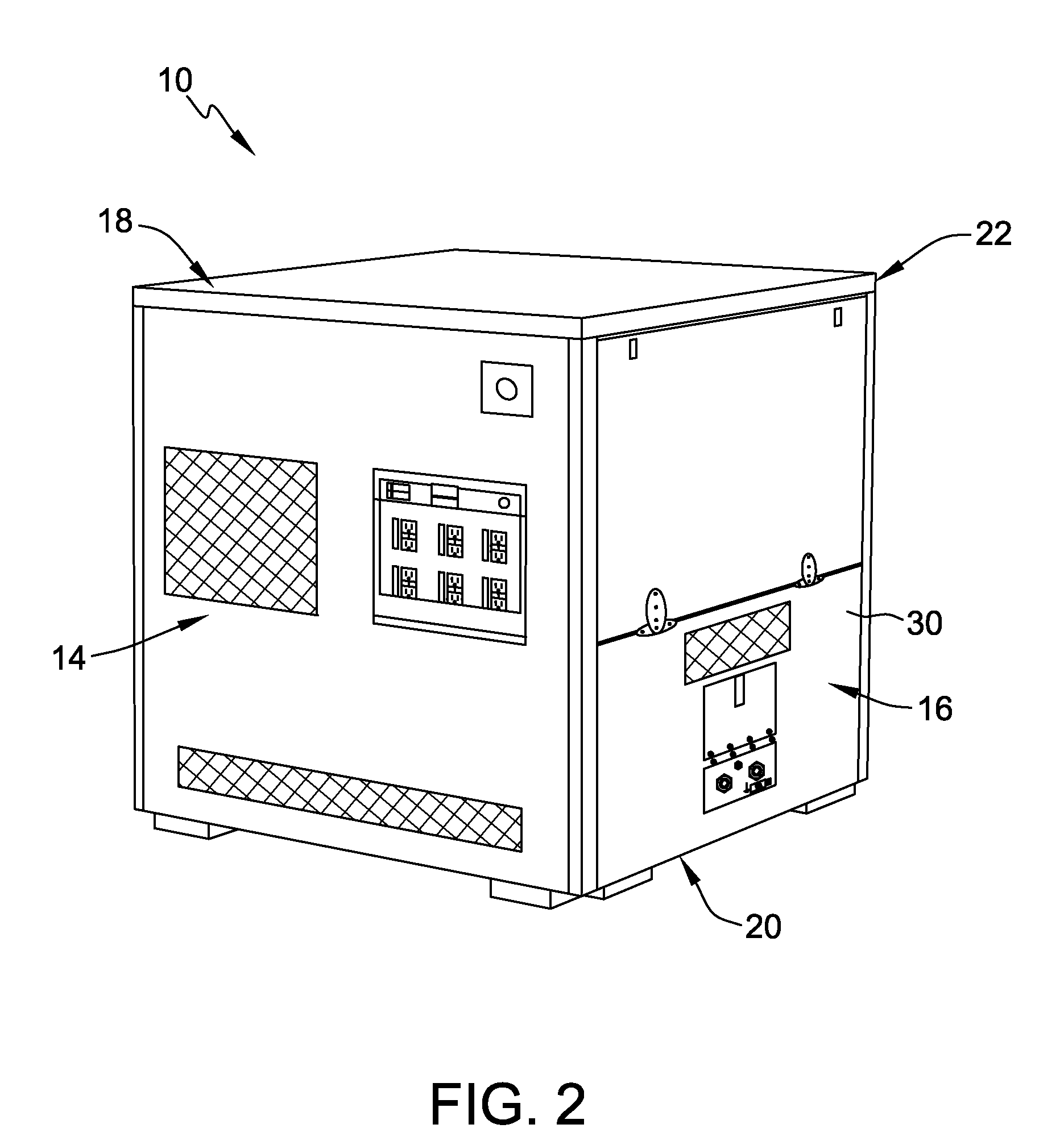
[0018]The following detailed description illustrates embodiments of the invention by way of example and not by way of limitation. The description clearly enables one skilled in the art to make and use the disclosure, describes several embodiments, adaptations, variations, alternatives, and uses of the disclosure, including what is presently believed to be the best mode of carrying out the disclosure. The disclosure is described as applied to an exemplary embodiment, namely, a self-contained portable energy supply module that provides a cost efficient and convenient method to provide electricity and hot water to areas where such luxuries are unavailable. However, it is contemplated that this disclosure has general application to power generation systems in industrial, commercial, and residential applications.

[0019]FIG. 1 is a perspective view of an exemplary energy supply module 10 illustrating a first side 12 and a first end 14. FIG. 2 is a rotated perspective view of energy supply ...


PUM

PropertyMeasurementUnit
storage areaaaaaaaaaaa
electrical energyaaaaaaaaaa
mechanical energyaaaaaaaaaa

Abstract

An energy supply module is configured to provide at least one of electricity and hot water to at least one load coupled thereto. The energy supply module includes a plurality of frame members that define an upper level and a lower level. The energy supply module also includes an engine positioned on the upper level and a generator coupled to the engine and also positioned on the upper level. The generator is configured to generate a supply of electricity for distribution to the at least one load. The energy supply module further includes a hot water heater positioned on the upper level, wherein the hot water heater is configured to provide a supply of hot water to the at least one load.

Description

BACKGROUND OF THE INVENTION[0001]This invention relates to an energy supply module for providing electrical energy to at least one load, and more specifically, to a self-contained, portable energy supply module that facilitates cost efficient and rapid deployment to a desired location.[0002]At least some known electrical generators are used to convert mechanical energy into electrical energy. For example, a generator may be used as a backup power source when a primary power source has failed or as a primary power source where traditional utility generated power is either unavailable or doesn't provide sufficient reliability or quantity. Further, at least some known electrical generators are portable for transport to locations where supplemental electricity is required, such as construction or industrial sites, entertainment events, and disaster recovery sites. Conventional generators used for such purposes are often of such size such that a standard-sized truck is only able to trans...

Claims


Application Information

Patent Timeline
Patent Type & Authority Patents(United States)
IPC IPC(8): B60L1/02F24H9/14F24H1/08F24H9/02F24H9/00H02K5/02F24H1/06H02K7/18F03G7/08F02B63/04A47J31/54F24H1/18A47J27/00H02K15/00F02C6/18F02C6/00F01K17/02F01K15/00F24D18/00
CPCF24H1/06F24H1/08F24H9/0094F24H9/02F24H9/148H02K5/02H02K15/00F02B63/044F24H2240/06Y10T29/49009F24D18/00F24D2101/70F24D2101/10Y02B30/00
Inventor JUSTUS, CHARLES ROBERT
Owner JUSTUS CHARLES ROBERT
Why Eureka
Try Eureka