Temperature control device for the temperature control of a battery and method for the production of a temperature control device

a temperature control device and battery technology, applied in the direction of batteries, cell components, lighting and heating apparatus, etc., can solve the problems of cell thereby producing a high loss performance and irreversible damag

Inactive Publication Date: 2016-04-19
MAHLE INT GMBH
View PDF9 Cites 5 Cited by
  • Summary
  • Abstract
  • Description
  • Claims
  • Application Information

AI Technical Summary

Benefits of technology

[0006]It is therefore an object of the present invention to create an improved temperature control device for the temperature control of a battery, as well as an improved method for the production of a temperature control device for the temperature control of a battery.
[0010]Advantageously a savings in tool costs can be achieved by using a flat plate as the second side of the heat exchanger. In addition, a flat second side enables a good thermal connection of the battery to the heat exchanger.
[0011]A design system and production system for a battery cooler in two-layer design (2L-plate) is described, which can be extended with flat tubes. The system has a high flexibility and thus enables a cost-efficient production of various battery cooler dimensions.
[0012]Since electric or hybrid vehicles are currently still being produced in small production runs, a standardization of cells or complete batteries has not yet progressed greatly, which leads to many different battery coolers with small production runs and makes scale-up effects more difficult. Therefore the connection presented here avoids production methods that are otherwise usual in automotive technology, such as stamping tools or embossing tools which are manufactured for a cooler type in a proprietary manner. By these means the temperature control device can be produced in a cost-effective manner.
[0017]The lower part can be connected to the upper part mechanically between the flat tube and the further flat tube in the area of the sealing edge. To this end a mechanical connection can be created before the soldering. The lower part can clamp and fix the flat tubes to the upper part by means of the mechanical connection, so that the tubes can no longer slip.
[0019]The lower part can have at least one embossed bump that is arranged on the upper side of the lower part. A bump can be a boss-shaped elevation on the upper side. The bump can be embossed as a boss-shaped depression on the underside. The bump can extend up to the underside of the upper part. Then the bump can have a contact surface to the underside of the upper part and can be connected to the upper part in a fluid-tight manner at the contact area. The bump can endow the temperature control device with a greater stability. Likewise the bump can lead to an improved heat removal.

Problems solved by technology

This is based on the fact that the efficiency of the battery cells drops very sharply when the temperature falls below a suitable operating temperature, and the cells thereby produce a high loss performance.
On the other hand, above a suitable operating temperature range, processes proceed within the cells that lead to irreversible damage.

Method used


Image

  • Temperature control device for the temperature control of a battery and method for the production of a temperature control device
  • Temperature control device for the temperature control of a battery and method for the production of a temperature control device
  • Temperature control device for the temperature control of a battery and method for the production of a temperature control device

Examples


Embodiment Construction

[0037]In the description below of the preferred exemplary embodiments of the present invention, the same or similar reference numbers are used for the elements that are shown in the various drawings and act in a similar manner, wherein a repeated description of these elements is omitted.

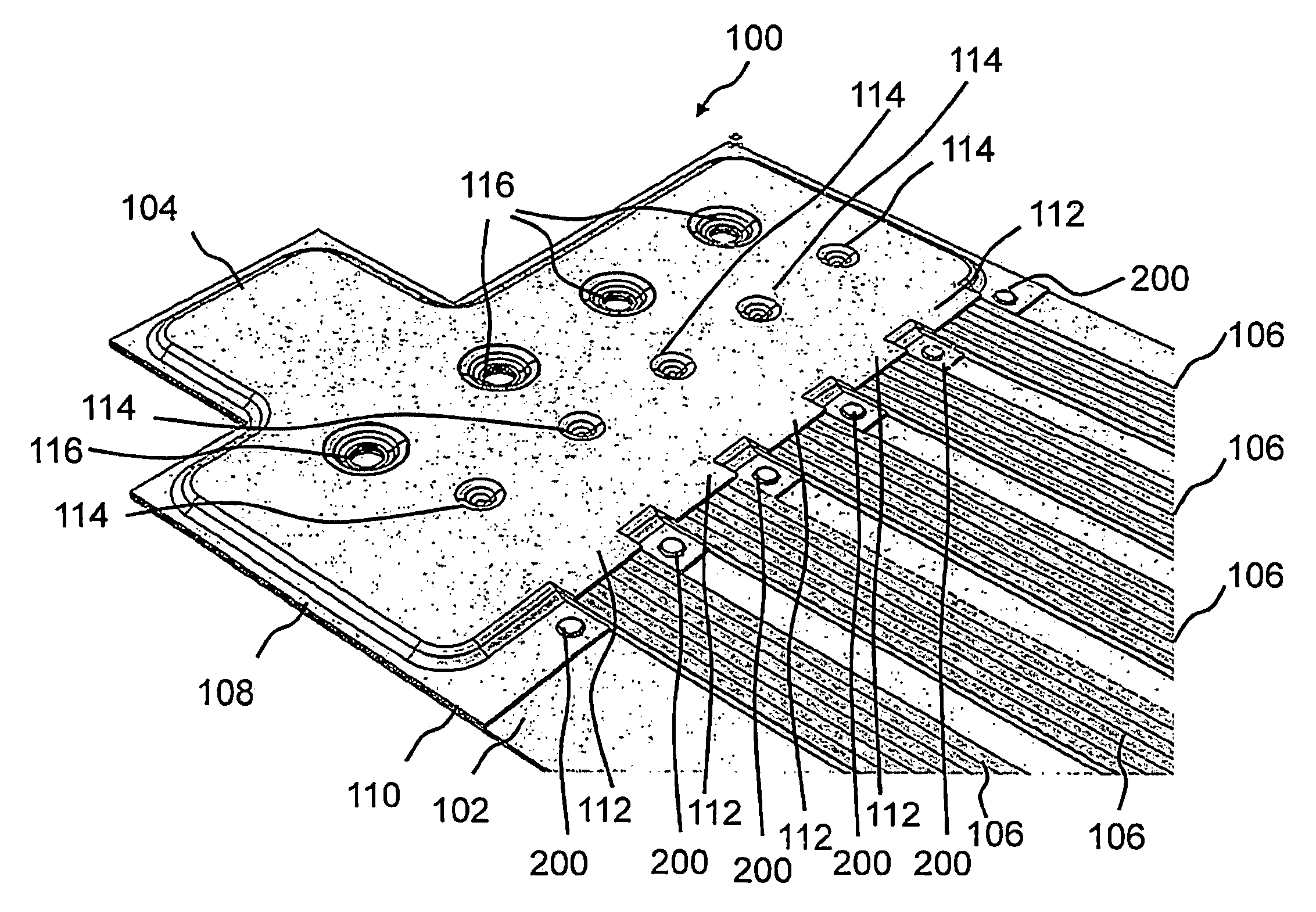
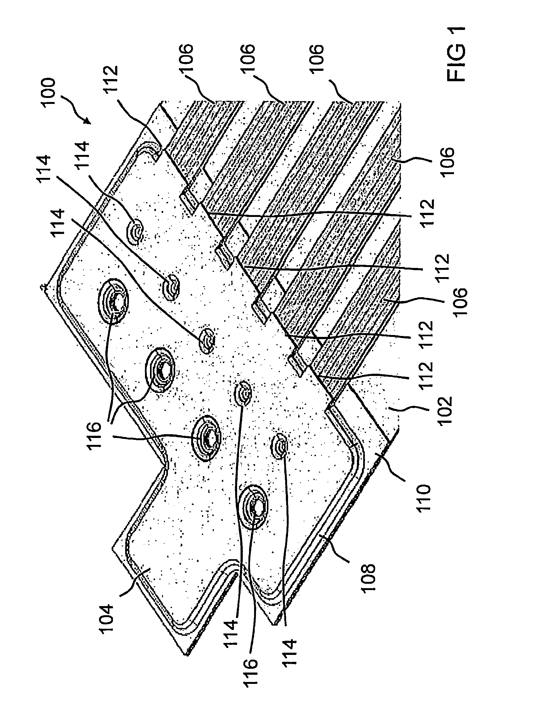
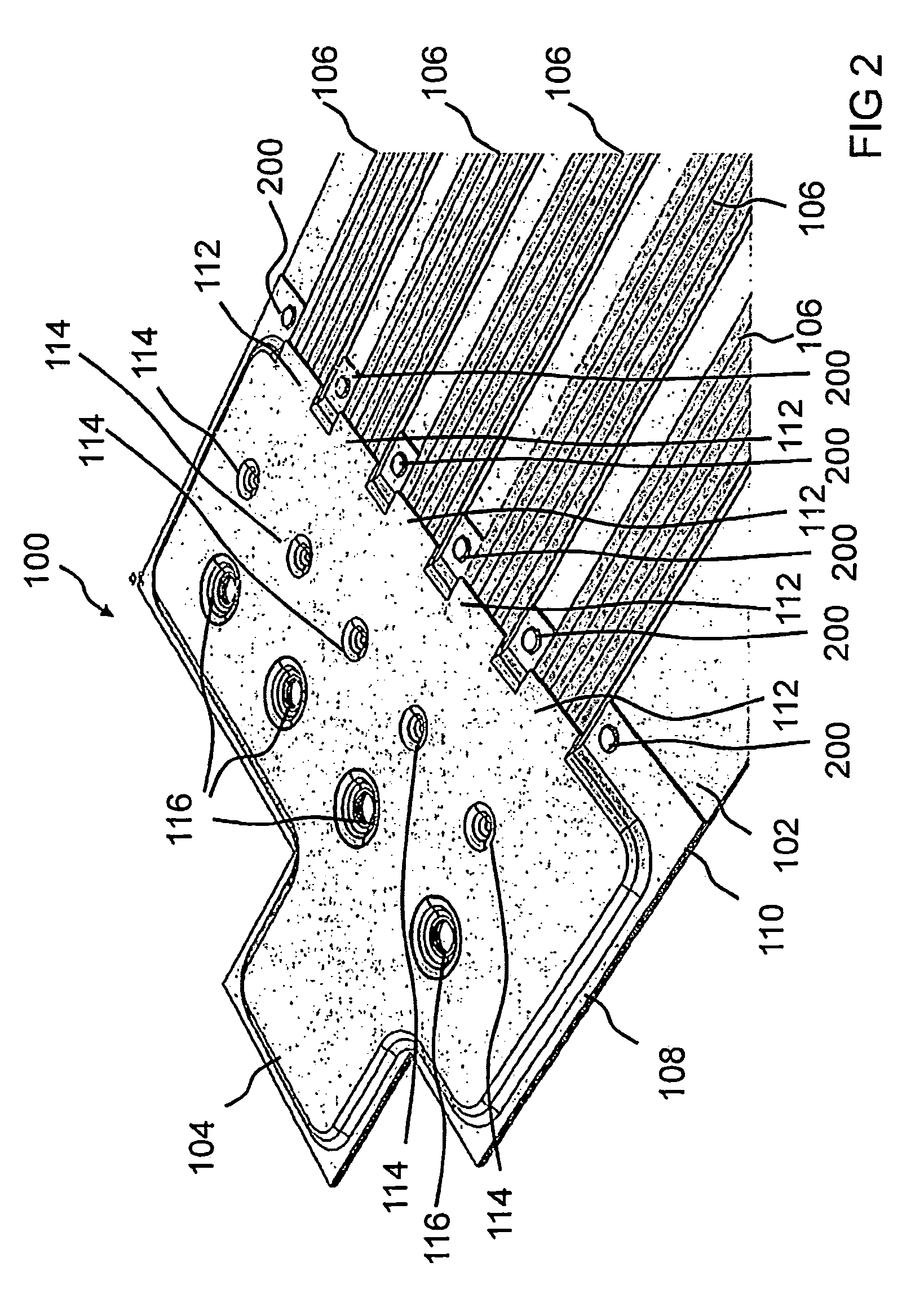
[0038]FIG. 1 shows a view of a section of a temperature control device 100 for the temperature control of a battery according to an exemplary embodiment of the present invention. The temperature control device 100 is joined together in a fluid-tight manner from several individual parts by means of a soldered connection. In this exemplary embodiment the temperature control device comprises an upper part 102, at least one lower part 104 as well as five flat tubes 106. The upper part 102 is embodied as a flat plate without raised structures. In the section shown, the upper part 102 has a contour embodied as a right angle as an outline, wherein at a narrow side of a rectangular body of the upper part 102...


PUM

PropertyMeasurementUnit
temperatureaaaaaaaaaa
areaaaaaaaaaaa
operating temperatureaaaaaaaaaa

Abstract

A temperature control device is provided for the temperature control of a battery. The temperature control device has an upper part with an upper side and an underside, which has on the upper side a thermal interface to the battery. Furthermore, the temperature control device has at least one lower part, which has an embossed structure in order to embody a sealing edge and to embody a cavity for guiding temperature control fluid. The sealing edge is arranged on an upper side of the lower part, and is connectable to the underside of the upper part in a fluid-tight manner.

Description

[0001]This nonprovisional application claims priority under 35 U.S.C. §119(a) to German Patent Application No. DE 10 2011 078 897.2, which was filed in Germany on Jul. 8, 2011, and which is herein incorporated by reference.BACKGROUND OF THE INVENTION[0002]1. Field of the Invention[0003]The present invention relates to a temperature control device for the temperature control of a battery, as well as to a method for the production of a temperature control device for the temperature control of a battery.[0004]2. Description of the Background Art[0005]With the use of modern high-performance batteries constructed from a number of individual cells, such as e.g. accumulators or secondary batteries for electric or hybrid vehicles, care must be taken that the temperature of the battery during operation is within a certain interval, in order to ensure the efficiency, functionality and safety of the device. This is based on the fact that the efficiency of the battery cells drops very sharply w...

Claims


Application Information

Patent Timeline
Patent Type & Authority Patents(United States)
IPC IPC(8): F28F3/12H01M10/613H01M10/625H01M10/6556
CPCH01M10/613H01M10/625H01M10/6556H01M2220/20Y10T29/49108Y02E60/10
Inventor HIRSCH, STEFAN
Owner MAHLE INT GMBH
Why Eureka
Try Eureka