Electrical receptacle connector and electrical plug connector

a technology of electrical receptacles and connectors, applied in the direction of coupling device connections, coupling protection earth/shielding arrangements, two-part coupling devices, etc., can solve the problems of insufficient usb 2.0 transmission rate, negatively affecting the performance of electrical connectors, and insufficient emi shielding provided by conventional shells, so as to achieve further reduction of electromagnetic interference and reduce the amount of resistance

Active Publication Date: 2016-04-19
ADVANCED CONNECTEK INC
View PDF22 Cites 63 Cited by
  • Summary
  • Abstract
  • Description
  • Claims
  • Application Information

AI Technical Summary

Benefits of technology

[0008]In conclusion, since the conductive contact members or spring members of the electrical receptacle connector are connected to the second tubular portion of the electrical plug connector when the electrical plug connector is plugged into the electrical receptacle connector, a low-impedance grounding path is effectively established between the metal shell of the electrical plug connector and the metal shell of the electrical receptacle connector such that the electromagnetic interference (EMI) can be further reduced so as to meet the relevant EMI regulations. In order to accommodate end users with the attribute of usability, durability, and robustness of USB connectors and also meet the requirement of the connector insertion force lower than extraction force when inserting a plug connector into a receptacle connector or extracting a plug connector from a receptacle connector, the amount of resistance between the metal shell of the electrical plug connector and the conductive contact members or spring members can be reduced through reducing the contact areas between the surfaces of the metal shell of the electrical plug connector and the conductive contact members or spring members. In addition, the amount of resistance between the metal shell of the electrical plug connector and the conductive contact members or spring members can be controlled through the geometry, material selection, surface finishing and sizing of the conductive contact members or spring members. Furthermore, because the upper-row plate terminals and the lower-row plate terminals of the electrical receptacle connector are arranged upside down, and the arrangement sequence of the upper-row plate terminals are left-right reversal with respect to the arrangement sequence of the lower-row plate terminals, the electrical plug connector is inserted into the interior of the electrical receptacle connector with the terminals of the electrical plug connector contacting with the upper-row plate terminals when being plugged by a forward orientation, and the electrical plug connector is inserted into the interior of the electrical receptacle connector with the terminals of the electrical plug connector contacting with the lower-row plate terminals when being plugged by a reverse direction. Therefore, the inserting orientation of the electrical plug connector is not limited, and can be forwarded or reversed, upon plugging into the electrical receptacle connector according to the present invention.

Problems solved by technology

The transmission rate of USB 2.0 is not sufficient.
An increase in electromagnetic coupling may generate unwanted noise or crosstalk that negatively affects the performance of the electrical connector.
However, due to increasing the speed rate of signals being transmitted through the electrical connector assemblies when a plug connector is plugged into a receptacle connector, the EMI shielding provided by conventional shell is proving to be inadequate.
In addition, in order to accommodate end users with the attribute of usability, durability, and robustness of USB connectors and also meet the requirement of the connector insertion force lower than extraction force when inserting a plug connector into a receptacle connector or extracting a plug connector from a receptacle connector, the existing USB connectors could not meet all above-mentioned requirements.

Method used


Image

  • Electrical receptacle connector and electrical plug connector
  • Electrical receptacle connector and electrical plug connector
  • Electrical receptacle connector and electrical plug connector

Examples


Embodiment Construction

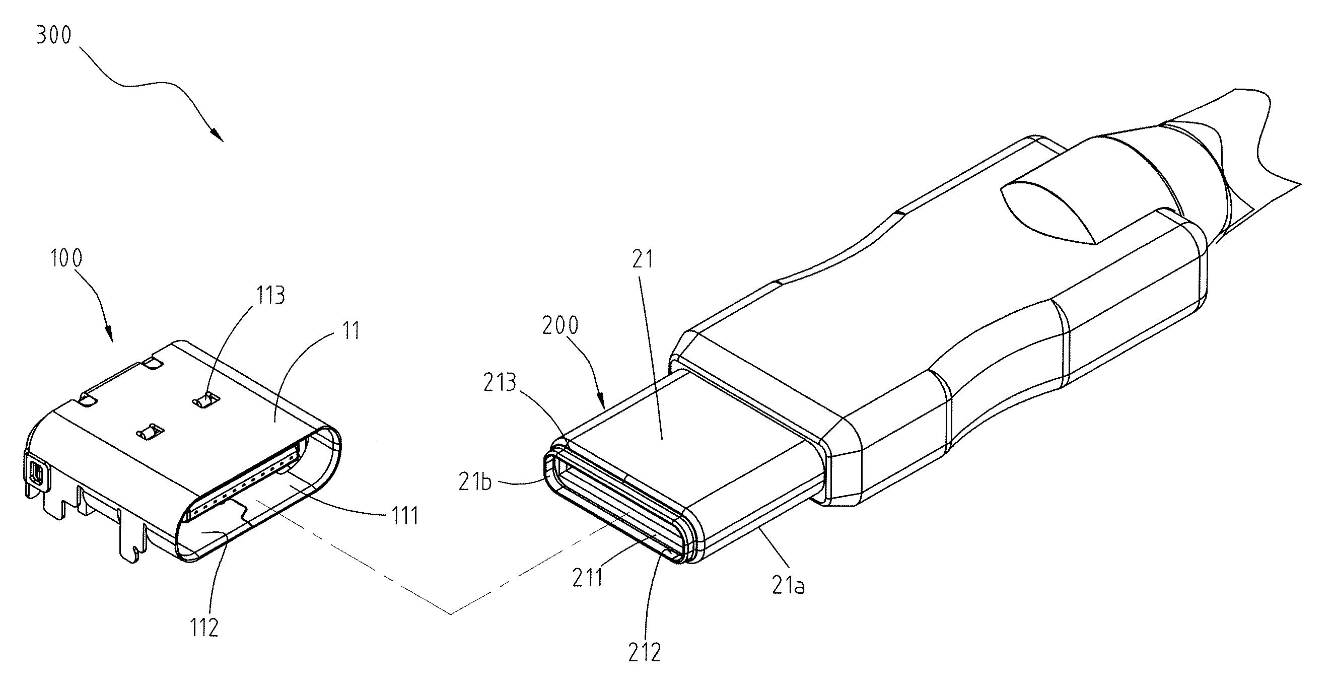
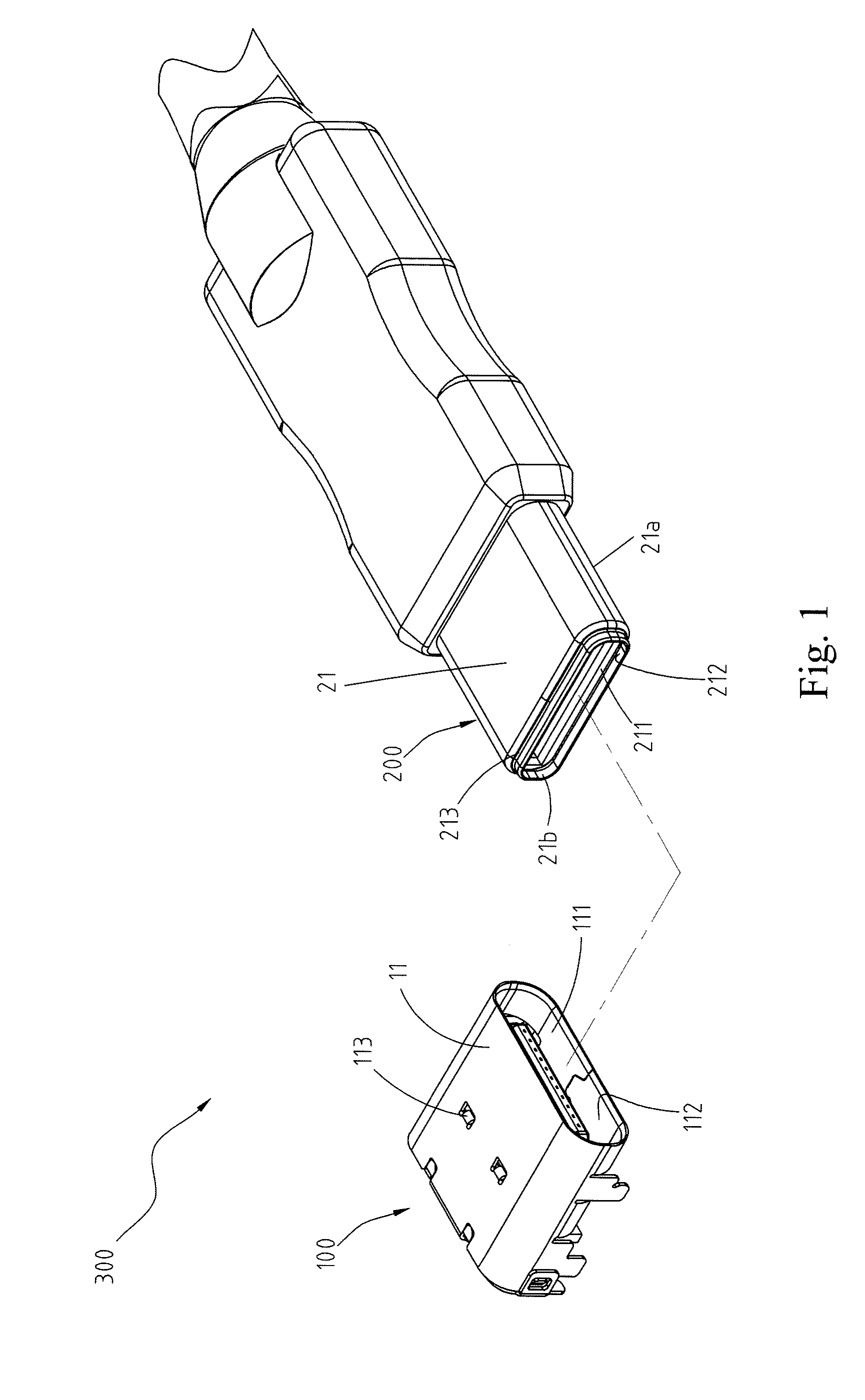
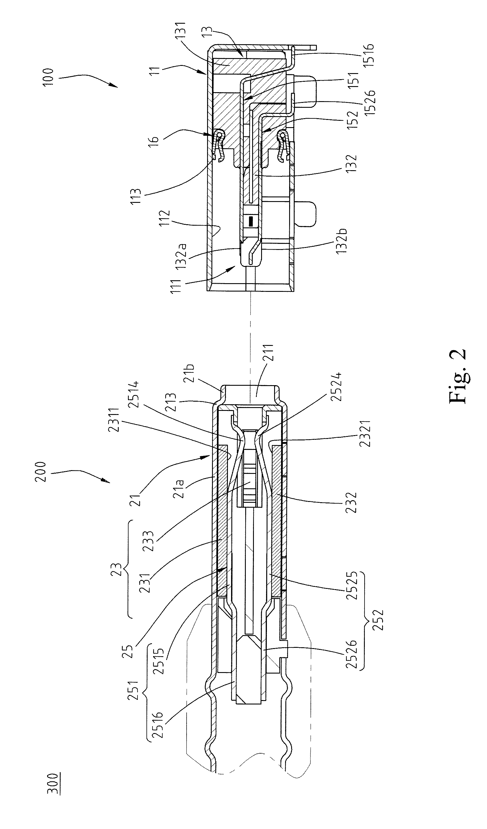
[0026]Referring to FIGS. 1, 2 and 3, which illustrate an exemplary embodiment of an electrical connector assembly 300 according to the present invention. FIG. 1 illustrates an exploded perspective view of an electrical connector assembly 300. FIG. 2 illustrates a cross-sectional view of the electrical connector assembly 300 of FIG. 1, showing an electrical receptacle connector 100 and an electrical plug connector 200. FIG. 3 illustrates a cross-sectional view of the electrical connector assembly 300, showing the electrical receptacle connector 100 mated with the electrical plug connector 200.

[0027]FIGS. 4 and 5 illustrate an exemplary embodiment of the electrical receptacle connector 100 according to the present invention. FIG. 4 clearly illustrates the perspective view showing that a plurality of conductive contact members or spring members 16 are located inside the electrical receptacle connector 100 and arranged on a top side of an insulation housing 13 while a metal shell 11 is ...


PUM


Abstract

An electrical receptacle connector provided to connect with an electrical plug connector. The electrical receptacle connector includes a metal shell, an insulation body and a the conductive contact members. The conductive contact members are disposed at the insulation body to connect with the metal shell. The electrical plug connector includes a metal shell and a tubular portion disposed at a front portion of the metal shell. When the electrical plug connector is plugged into the electrical receptacle connector, the surface of the tubular portion of the electrical plug connector is in contact with the conductive contact members.

Description

CROSS-REFERENCES TO RELATED APPLICATIONS[0001]This non-provisional application claims priority under 35 U.S.C. §119(a) on Patent Application 103206940 and 103132680, filed in Taiwan, R.O.C. on Apr. 21, 2014 and Sep. 22, 2014, the entire contents of which are hereby incorporated by reference.FIELD OF THE INVENTION[0002]The present invention relates to an electrical connector, and more particular to an electrical receptacle connector and an electrical plug connector correspondingly connecting thereof.BACKGROUND[0003]Generally, Universal Serial Bus (USB) is a serial bus standard to the PC architecture with a focus on computer interface, consumer and productivity applications. The existing Universal Serial Bus (USB) interconnects have the attributes of plug-and-play and ease of use by end users. Now, as technology innovation marches forward, new kinds of devices, media formats and large inexpensive storage are converging. They require significantly more bus bandwidth to maintain the int...

Claims


Application Information

Patent Timeline
Patent Type & Authority Patents(United States)
IPC IPC(8): H01R13/648H01R13/6581H01R24/60H01R107/00
CPCH01R13/6581H01R24/60H01R2107/00
Inventor MACDOUGALL, ALANWANG, WEN-YUKAO, YA-FEN
Owner ADVANCED CONNECTEK INC
Why Eureka
Try Eureka