
Fuel delivery device

a technology of fuel delivery and fuel injection pump, which is applied in the direction of liquid fuel engine, fuel injecting pump, machine/engine, etc., can solve the problems of high drive power demand of pump and electrical control and sensor device, and achieve the effect of reducing development effor

Active Publication Date: 2016-05-03
ROBERT BOSCH GMBH
View PDF18 Cites 1 Cited by
  • Summary
  • Abstract
  • Description
  • Claims
  • Application Information

AI Technical Summary

Benefits of technology

[0003]The fuel delivery device according to the invention has the advantage that the supply pump has a variable displacement, so that a variable quantity of fuel can be delivered at a constant rotational speed. The facility for varying the fuel delivery quantity at a constant rotational speed makes it possible to eliminate the feedback control of the fuel delivery quantity via the electrical drive and to dispense with the control and sensor devices, thereby saving costs. The supply pump may be mechanically or electrically driven and is capable of varying its fuel delivery quantity at a constant rotational speed.
[0004]In a first advantageous embodiment of the fuel delivery device the supply pump delivers a variable quantity of fuel, which varies between a zero delivery quantity and a maximum quantity. The maximum quantity is determined by the maximum displacement of the supply pump. The wide range within which the fuel delivery quantity can vary allows an optimum adjustment of the fuel delivery quantity to the fuel demand in the high-pressure region. Additional components, such as the electrical drive of the supply pump, for example, an electrical control device for feedback control of the electrical drive or a metering unit (ZME), which adjusts the fuel delivery quantity to the demand of the high-pressure pump, are eliminated.
[0005]In an advantageous development of the method the adjustable displacement is regulated via a control pressure. No further external control devices need to be involved in order to adjust the fuel delivery quantity of the supply pump to the demand in the high-pressure region. Sensor units for registering the pressure are also eliminated, since the pressure does not have to be determined, but instead directly influences the delivery quantity. This reduces the cost outlay and simplifies the construction of the low-pressure circuit.
[0006]In a further advantageous development the control pressure is the fuel pressure on the delivery side of the supply pump. In this case the supply pump adjusts optimally to the fuel demand in the high-pressure region. No further components such as an overflow valve and metering unit need to be used. Since the quantity of fuel required by the high-pressure pump is always delivered by the supply pump and any excess fuel delivered does not have to be diverted, the fuel consumption is reduced.
[0008]A further advantage accrues if the control pressure is the fuel pressure in the return to the fuel tank. With this solution, too, the use of further components is reduced, since the metering unit can be dispensed with. The excess fuel delivered serves as control pressure, so that a different design of the supply pump control elements is possible.
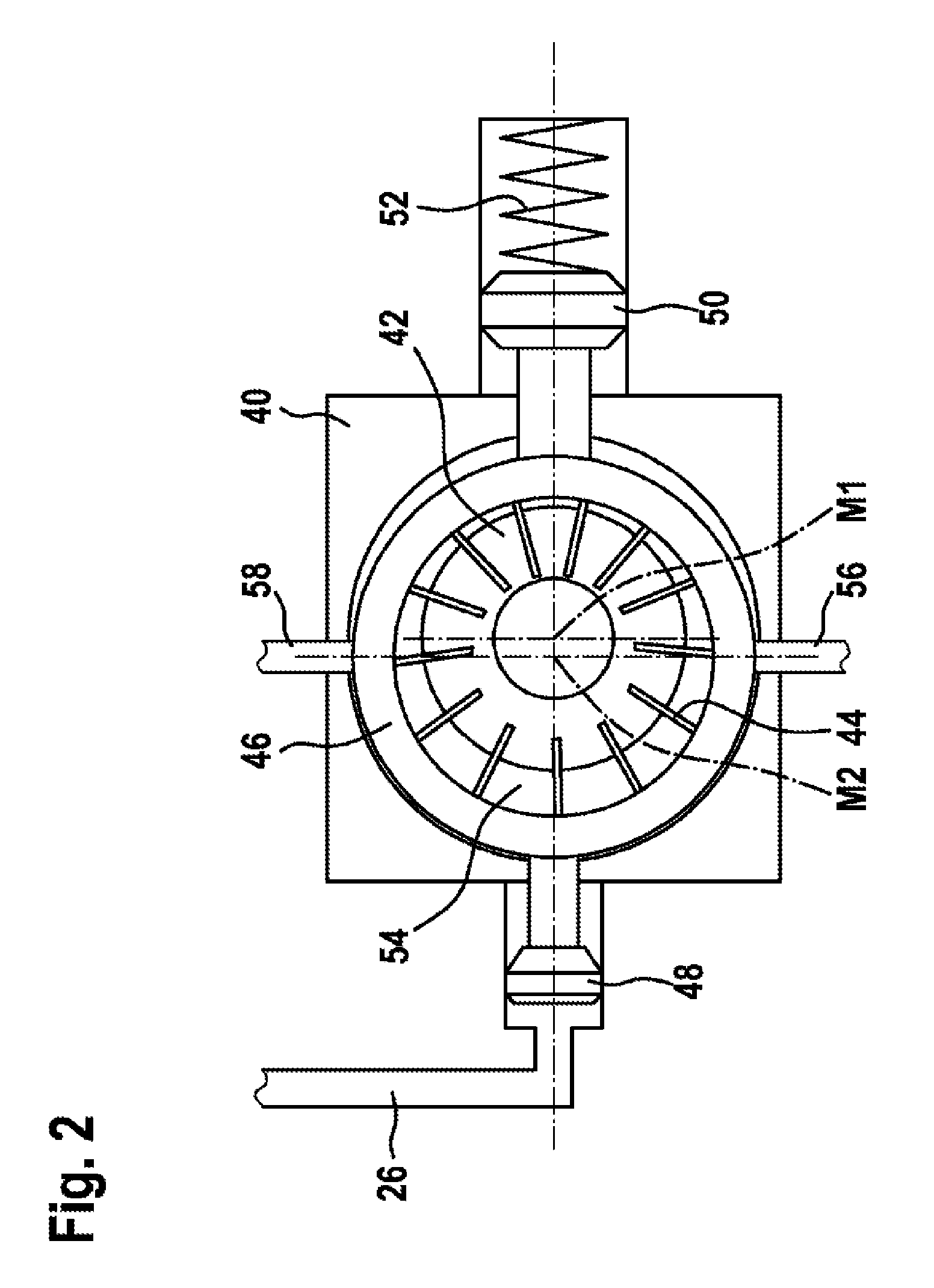
[0012]The use of a vane cell pump or an external gear pump or a roller cell pump or an internal gear pump or a pendulum-slider pump as supply pump with adjustable delivery is advantageous, since it is possible to resort to known types of pump and the development effort is reduced.

Problems solved by technology

This allows a fuel delivery quantity of the supply pump to be adjusted to the operating conditions but the pump has a high drive power demand and requires electrical control and sensor devices.

Method used


Image

  • Fuel delivery device
  • Fuel delivery device
  • Fuel delivery device

Examples


Embodiment Construction

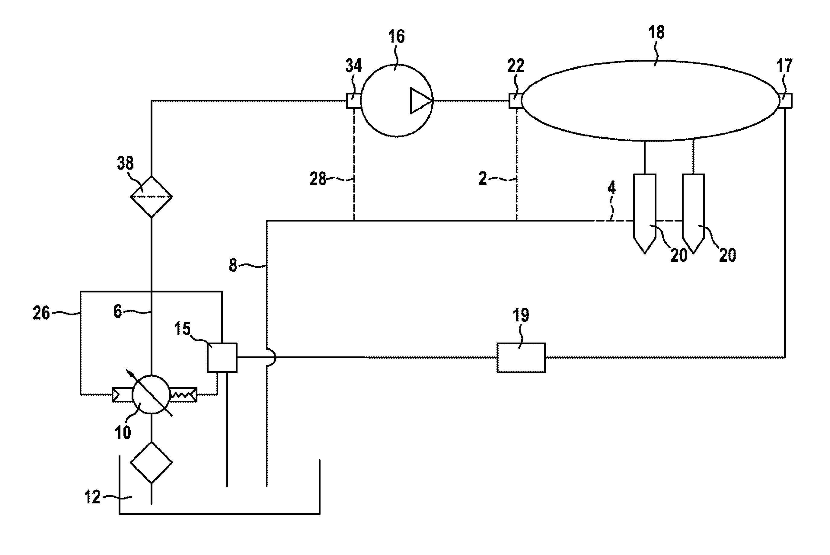
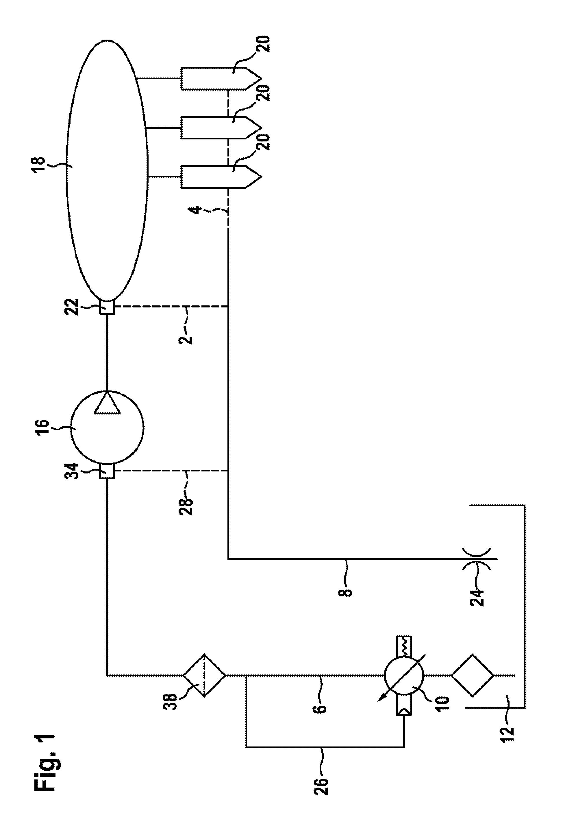
[0020]FIG. 1 shows a schematic representation of a fuel delivery device according to a first exemplary embodiment of the invention. The fuel delivery device comprises a supply pump 10, which sucks in fuel from a fuel tank 12. The supply pump 10 serves to deliver fuel to the suction side of at least one high-pressure pump 16, which is likewise an integral part of the fuel delivery device. The supply pump 10 may be mechanically driven by the engine or the high-pressure pump via a coupling, gearwheel or toothed belt. Alternatively the supply pump 10 may comprise an electrical drive, which can be operated with a variable output and hence a variable rotational speed or with a constant output and rotational speed.

[0021]At least the one high-pressure pump 16 serves to deliver fuel into a high-pressure region 18 of the fuel delivery device, which comprises a high-pressure accumulator 18, for example. From the high-pressure region 18 one or more injectors 20 are supplied with fuel, an inject...


PUM


Abstract

The invention proposes a fuel delivery device for a fuel injection device of an internal combustion engine, having a delivery pump (10) and having at least one high-pressure pump (16). By means of the delivery pump (10), fuel from a storage container (12) is delivered to the suction side of the high-pressure pump (16), and fuel is delivered into a high-pressure region (18) by the high-pressure pump (16). The delivery pump (10) has an adjustable displacement volume, which means that a variable quantity of fuel can be conveyed at the same rotational speed.

Description

BACKGROUND OF THE INVENTION[0001]The invention relates to a fuel delivery device for a fuel injection of an internal combustion engine.[0002]Such a fuel delivery device and the working principle thereof has already been disclosed by the series of publications on a diesel common rail injection system (ISBN-978-3-86522-010-3) of Robert Bosch GmbH or EP 1 195 514 A2. This fuel delivery device comprises an electrically driven supply pump, which delivers fuel to the suction side of a high-pressure pump. The high-pressure pump delivers fuel into a high-pressure region, from which at least one injector of the fuel injection device is supplied at least indirectly with fuel. An electrical control device is provided, which via a sensor device receives a signal for the pressure prevailing in the high-pressure region. The electrical control device serves for variable activation of the electrical drive of the supply pump, so that the fuel delivery quantity of the supply pump can be varied throug...

Claims


Application Information

Patent Timeline
Patent Type & Authority Patents(United States)
IPC IPC(8): F02M69/02F04C14/02F04C11/00F04C2/344F04C14/26F02M63/02F02M37/00F04C14/22
CPCF02M69/02F02M63/025F04C2/3442F04C11/00F04C14/02F04C14/26F02M37/00F04C14/22F02M59/20F02M59/22F02M59/36F02M63/02F02M69/54
Inventor KRAUSS, JOSTVEIT, GUENTERSOMMERER, ANDREASMEYER-SALFELD, STEFFEN
Owner ROBERT BOSCH GMBH
Learn More