
Object detection apparatus, object detection method, object detection program and device control system for moveable apparatus

a technology of object detection and object detection, applied in the field of object detection apparatus, an object detection method, an object detection program, etc., can solve the problems of difficult object detection, block matching method that detects disparity at substantially horizontal edges with lower precision, and cannot detect disparity at substantially horizontal edges

Active Publication Date: 2016-05-03
RICOH KK
View PDF20 Cites 10 Cited by
  • Summary
  • Abstract
  • Description
  • Claims
  • Application Information

AI Technical Summary

Benefits of technology

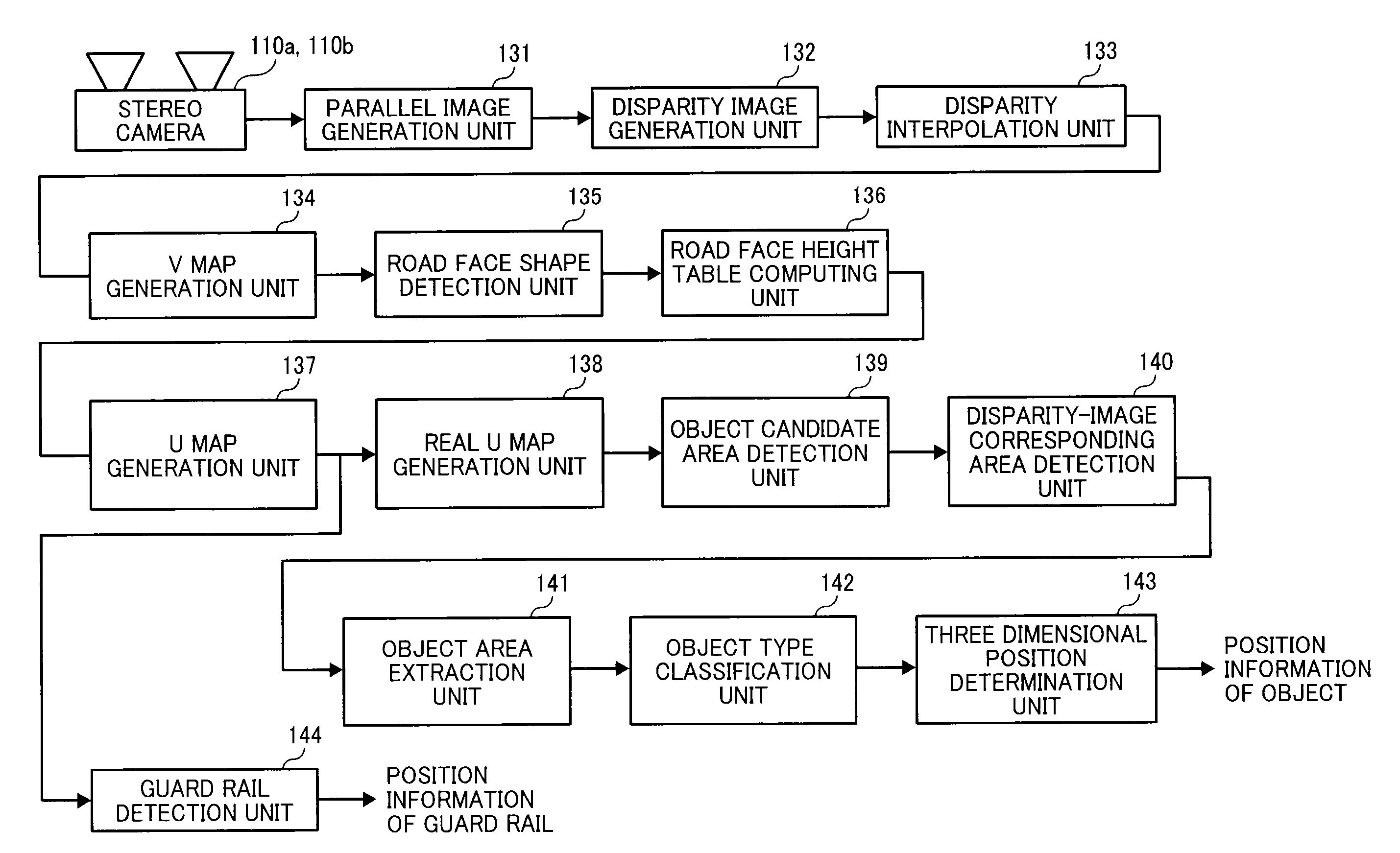
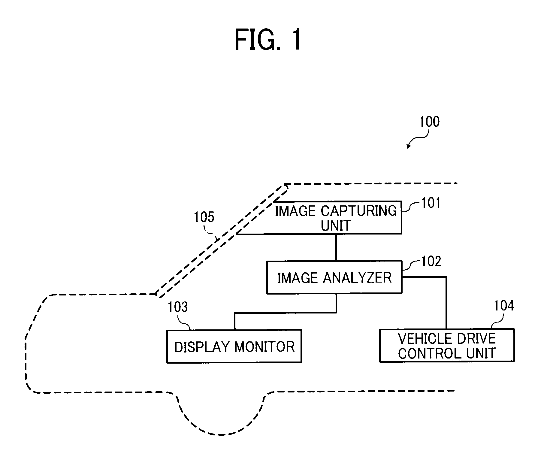
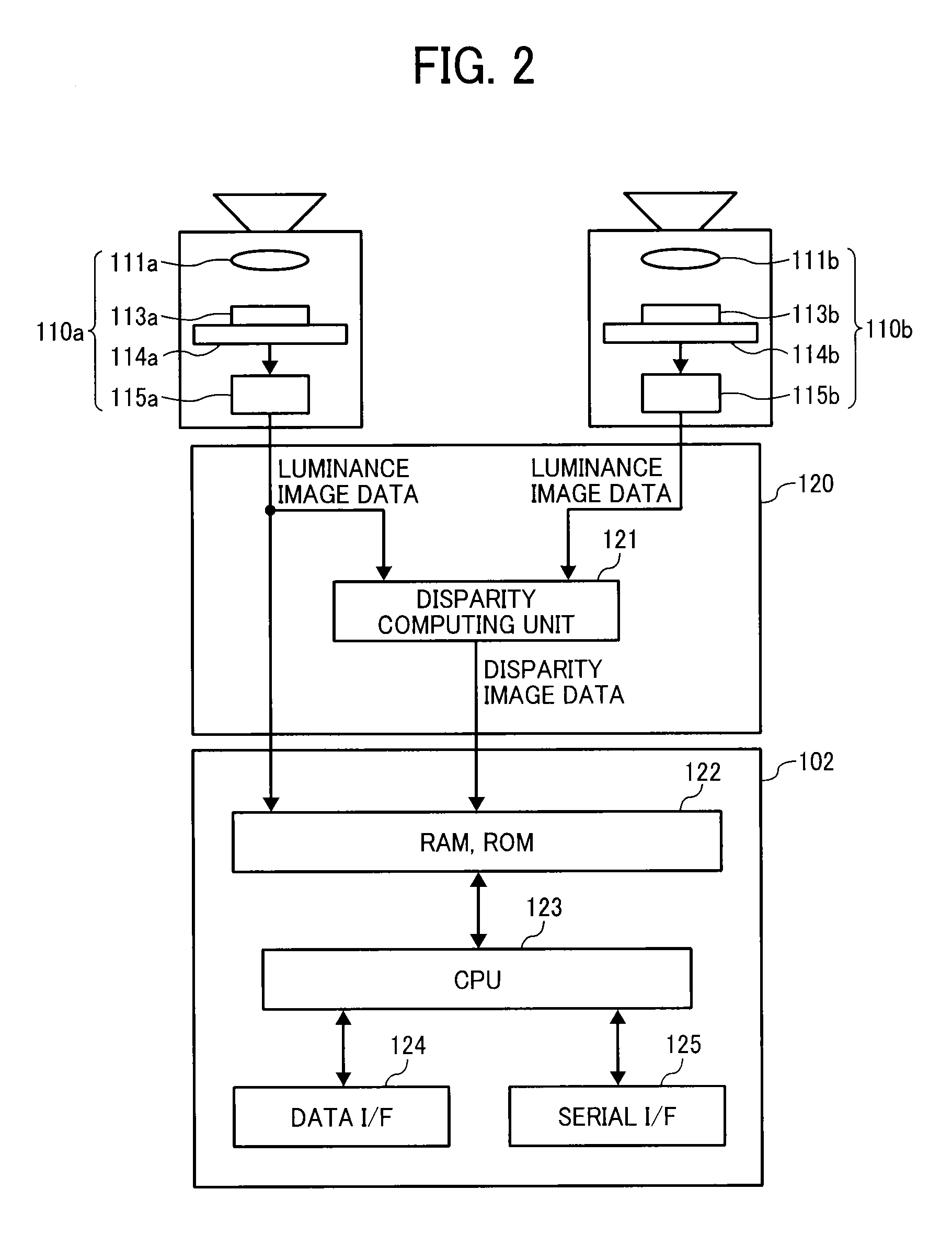
The present invention provides an object detection apparatus and method for detecting objects outside a moveable apparatus by capturing images and generating a disparity image. The apparatus includes a map generator to create a map of relative disparity values and a distance to the object based on the movement direction of the apparatus. An isolated area detection unit identifies isolated areas within the map and divides them into smaller sections based on the frequency profile. An object detector then detects objects within the divided isolated areas. The technical effect of this invention is to improve object detection and provide a more efficient and accurate way to identify objects outside a moveable apparatus.

Problems solved by technology

The block matching method can detect disparity at substantially vertical edges or strong texture with high precision, but the block matching method detects disparity at substantially horizontal edges with lower precision, in particular, cannot detect disparity at substantially horizontal edges.
Therefore, it is difficult to detect an object such as an ahead automobile as one object by stereo imaging.

Method used


Image

  • Object detection apparatus, object detection method, object detection program and device control system for moveable apparatus
  • Object detection apparatus, object detection method, object detection program and device control system for moveable apparatus
  • Object detection apparatus, object detection method, object detection program and device control system for moveable apparatus

Examples


example 1

VARIANT EXAMPLE 1

[0329]A description is given of a variant example of processing of the above described example embodiment (hereinafter, variant example 1). In the above described example embodiment, the height change of road face along the movement direction of vehicle (e.g., slope along the movement direction of vehicle) be detected, but the height change of road face along the width direction of road face (e.g., slope along the width direction of the road face) cannot be detected. The variant example 1 describes a configuration that can detect the slope along the width direction of the road face.

[0330]FIG. 57 is a flowchart showing the steps of a process of the variant example 1. FIG. 58 is a disparity image divided into two areas such as a left area and a right area, in which a straight line connecting the vanishing point V of the road face and the lowest-center point M of the disparity image is used as a boundary to divide the disparity image into the two areas. FIG. 59 is a di...

example 2

VARIANT EXAMPLE 2

[0335]A description is given of further other variant example (hereinafter, variant example 2) of the example embodiment. As to actual road faces, some road faces have a semicircular shape, in which the center portion in the width direction of road face is set higher than other portions to drain water from the road face effectively. This inclination in the width direction of the road face can be detected with enhanced precision by using the variant example 2.

[0336]FIG. 62 is a disparity image divided into three areas using a straight line L6 connecting a one-fourth (¼) point L (xsize / 4, ysize) in the left and the vanishing point V of a road face, and a straight line L7 connecting the one-fourth (¼) point R (3 / 4×xsize, ysize) in the right and the vanishing point V of the road face in the variant example 2. FIG. 63 is a disparity image set with one image scanning line L5 to the disparity image of FIG. 62. FIG. 64 is a disparity profile generated by performing a linear...


PUM


Abstract

An object detection apparatus mountable to a moveable apparatus for detecting an object existing outside the moveable apparatus by capturing a plurality of images using a plurality of imaging devices mounted to the moveable apparatus and generating a disparity image from the captured images includes a map generator to generate a map indicating a frequency profile of disparity values correlating a horizontal direction distance of the object with respect to a movement direction of the moveable apparatus, and a distance to the object in the movement direction of the moveable apparatus based on the disparity image, an isolated area detection unit to detect an isolated area based on the frequency profile, an isolated area divider to divide the isolated area into two or more isolated areas based on the frequency profile in the isolated area, and an object detector to detect an object based on the divided isolated area.

Description

CROSS-REFERENCE TO RELATED APPLICATION[0001]This application claims priority pursuant to 35 U.S.C. §119(a) to Japanese Patent Application Nos. 2014-081390, filed on Apr. 10, 2014 and 2015-062340, filed on Mar. 25, 2015 in the Japan Patent Office, the disclosure of which are incorporated by reference herein in their entirety.BACKGROUND[0002]1. Technical Field[0003]The present invention relates to an object detection apparatus, an object detection method, an object detection program, and a device control system for moveable apparatus to detect an object ahead of a moveable apparatus based on a plurality of captured images captured by a plurality of image capturing units, and to control devices mounted to the moveable apparatus using a detection result.[0004]2. Background Art[0005]Safety technologies have been developed for automobiles. For example, body structures of automobiles have been developed to protect pedestrians, and drivers / passengers when automobile collisions occur. Recent...

Claims


Application Information

Patent Timeline
Patent Type & Authority Patents(United States)
IPC IPC(8): G06K9/00H04N13/02G06T7/20G06T7/00G06T11/20G06K9/46H04N13/00H04N13/239
CPCG06K9/00791G06K9/46G06T7/20G06T11/206H04N13/0203G06T7/70G06K2009/4666G06T2207/10012G06T2207/10021G06T2207/30256G06T2207/30261H04N13/0239H04N2013/0081H04N13/239G06V20/56H04N13/204
Inventor TAKAHASHI, SADAOYOKOTA, SOICHIROISHIGAKI, TOMOKO
Owner RICOH KK
Learn More