
Motor power distribution apparatus

a technology for motors and power distribution devices, which is applied in the direction of electrical devices, dynamo-electric machines, windings, etc., can solve the problems small gaps may form between one or more of the insulating holders and the molded resin, and may not completely cohere, so as to achieve the effect of increasing the size of the power distribution system

Active Publication Date: 2016-05-03
NISSAN MOTOR CO LTD
View PDF25 Cites 7 Cited by
  • Summary
  • Abstract
  • Description
  • Claims
  • Application Information

AI Technical Summary

Benefits of technology

[0006]However, in some situations, the molded resin and the insulating holder may not completely cohere during the insertion molding process. Thus, small gaps may form between one or more of the insulating holders and the molded resin. Therefore, in order for the surface portion of the insulating holder to function as creepage insulation with respect to the metal bus bars instead of the molding resin functioning as solid insulation, the height of the wall of the insulating holder is raised. However, this increases the size of the power distribution system.
[0007]Accordingly, it is an object of the present invention to provide a motor power distribution apparatus that has a sufficient creepage insulation distance without the need to raise the height of the wall of any of the insulating holders.

Problems solved by technology

However, in some situations, the molded resin and the insulating holder may not completely cohere during the insertion molding process.
Thus, small gaps may form between one or more of the insulating holders and the molded resin.
However, this increases the size of the power distribution system.

Method used


Image

  • Motor power distribution apparatus
  • Motor power distribution apparatus
  • Motor power distribution apparatus

Examples


first embodiment

[0059]FIG. 14 illustrates an example of the shape of the first insulating holders 141 and the second insulating holders 142 in this second disclosed embodiment. As indicated, each of the first insulating holders 141 and the second insulating holders 142 has three slots 144, 145 and 146, and a positioning projection 143. In this example, the positioning projection of the first insulating holder 141 is denoted as 143A, and the positioning projection of the second insulating holder 142 is denoted as 143B as shown in FIG. 18 discussed below. As with the insulating holders 91 and 92 of the first embodiment, the slot 145 at the center is wider in the lateral direction and has greater slot depth as compared to the slots 144 and 146 at either side.

second embodiment

[0060]FIG. 15 illustrates examples of positions at which cross-sectional views are taken of the distribution structural component 10A in the Thus, FIG. 16 is a cross-sectional view taken at cross section position 16-16 in FIG. 15, and FIG. 17 is a cross-sectional view taken at cross section position 17-17 in FIG. 15.

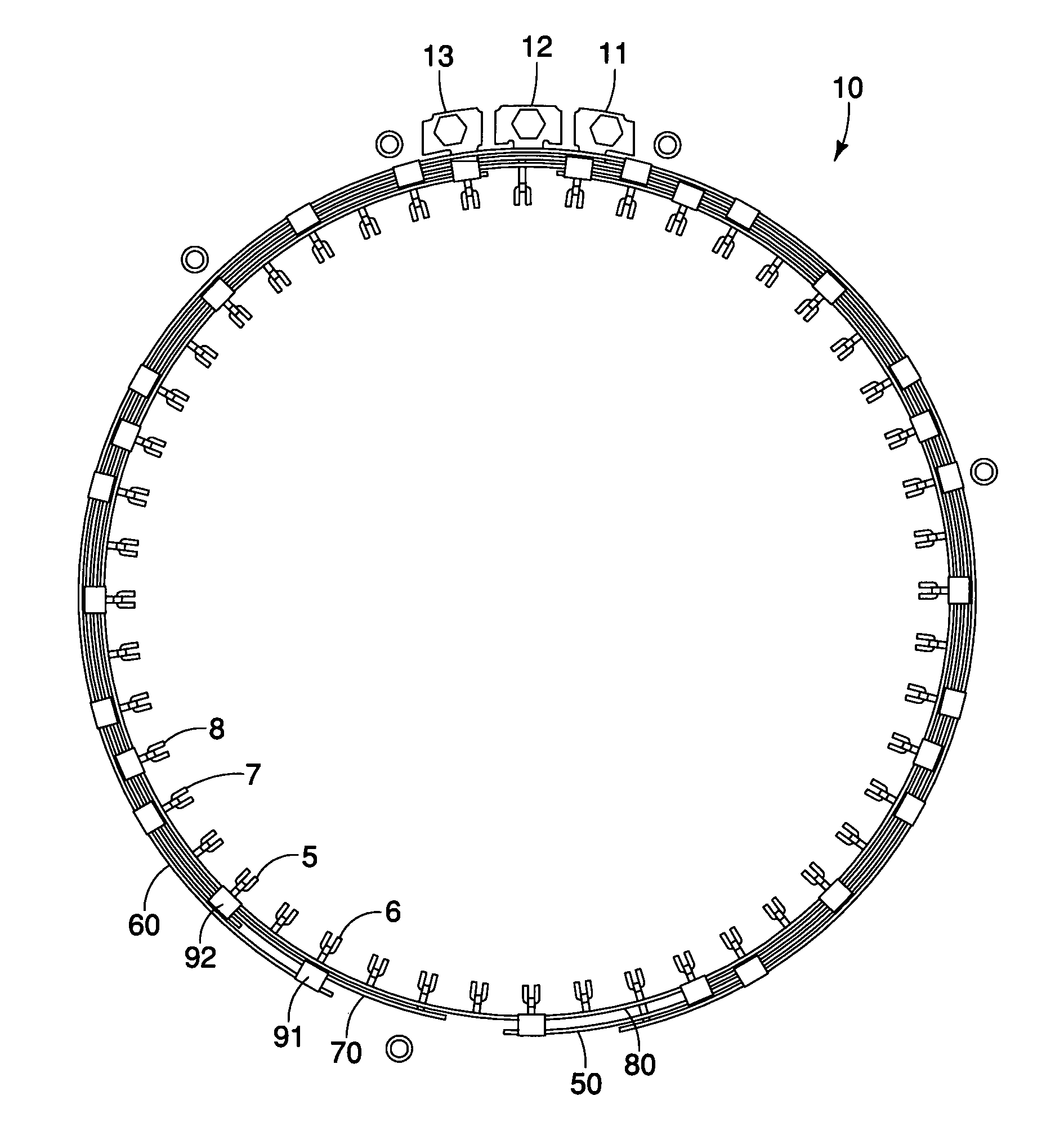
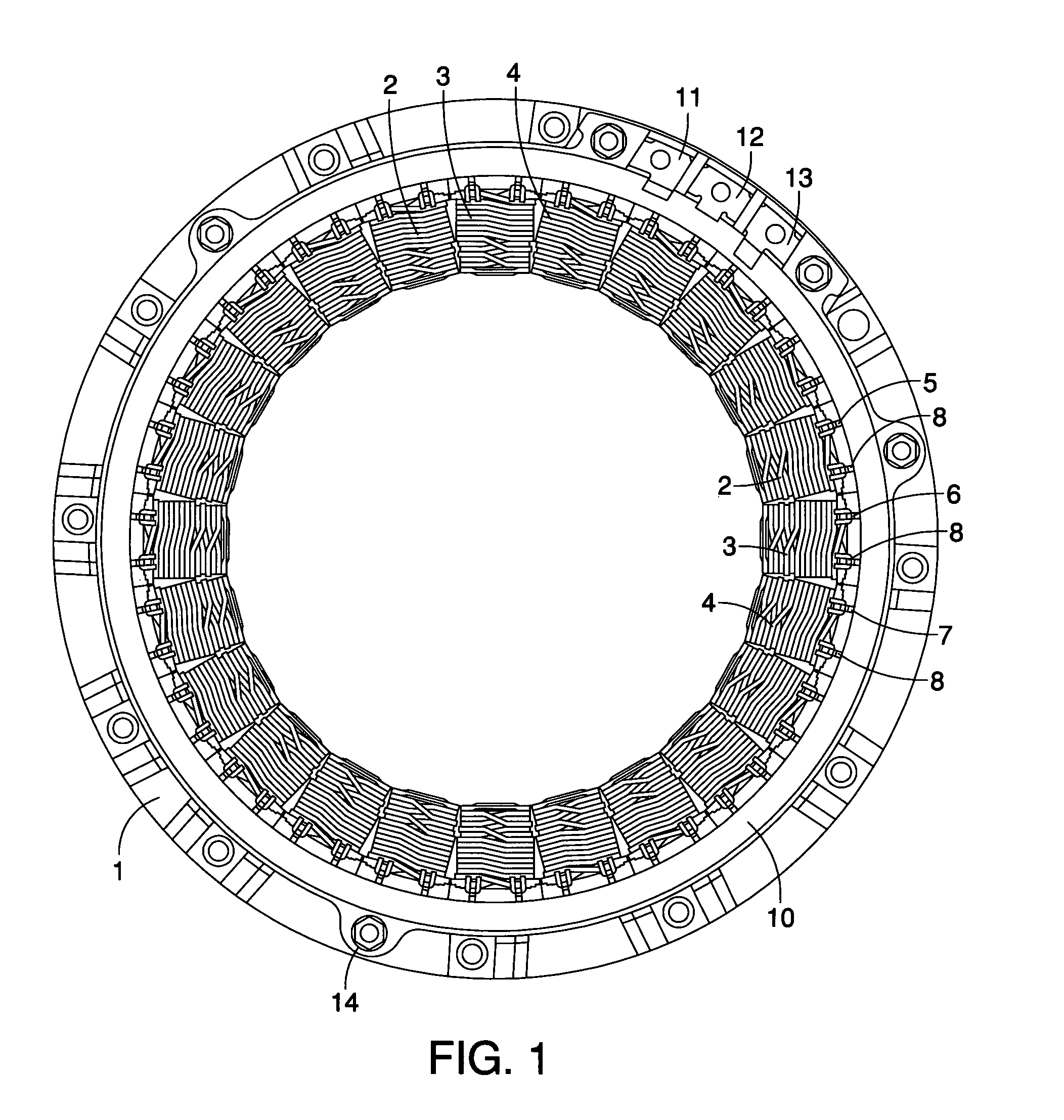
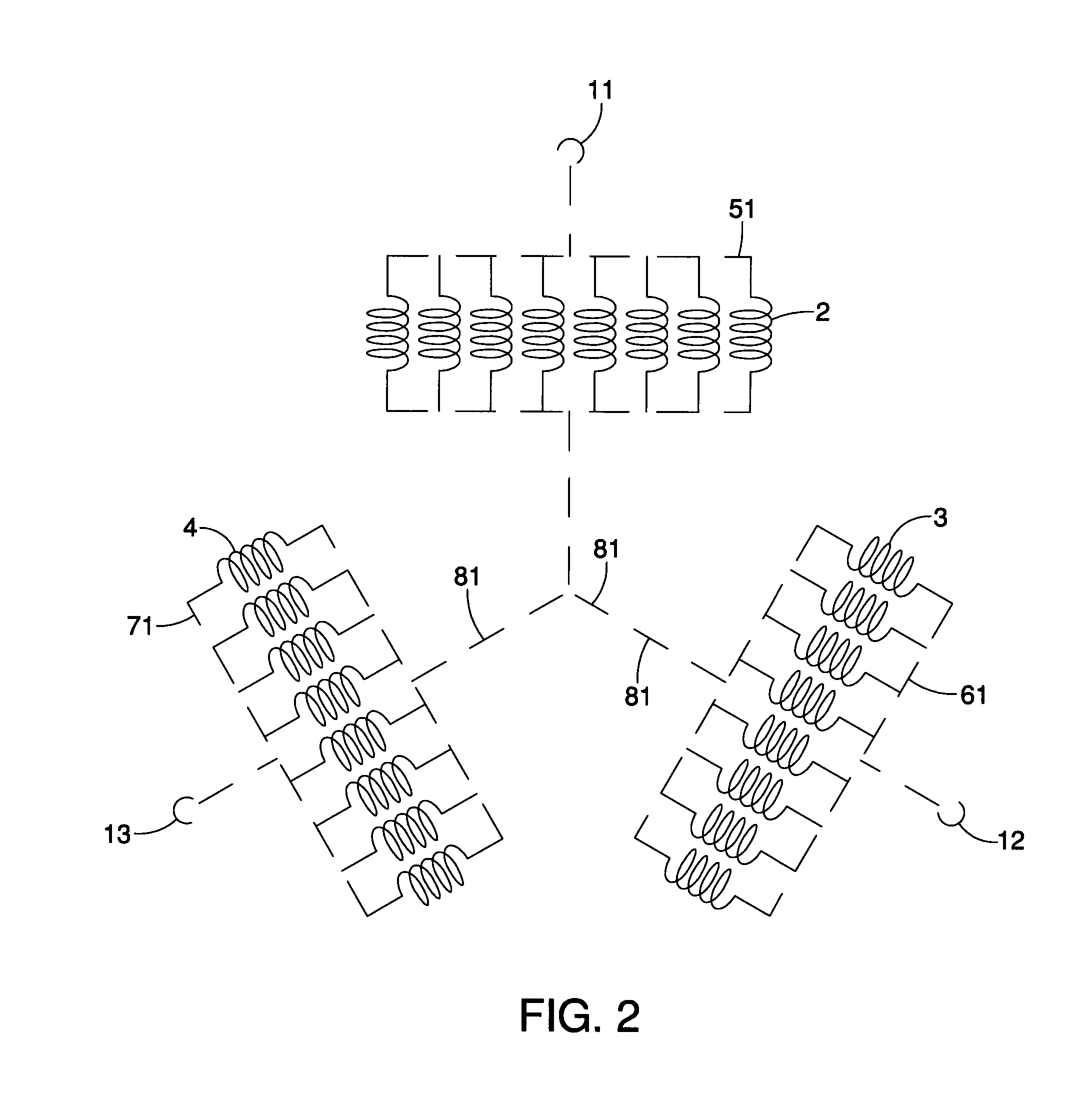
[0061]The mating relationships between the first insulating holders 141 and the buses of each of the phases are the same or similar as in the first embodiment. Specifically, as shown in FIG. 16, the slots 144 and 146 at the left and right edges, respectively, of the first insulating holders 141 mate with the V-phase bus 61 and the W-phase bus 71, respectively. Also, the wider, deeper slot 145 at the very center does not contact the U-phase bus 51. Thus, as in the first embodiment, the U-phase bus 51 is completely covered or substantially covered by the molded resin 120, which is an insulator. Likewise, the neutral bus 81 does not contact the first insulating holder 141....


PUM

PropertyMeasurementUnit
electric power distributionaaaaaaaaaa
power distributionaaaaaaaaaa
electricaaaaaaaaaa

Abstract

A motor power distribution apparatus includes first insulating holders and second insulating holders. The first insulating holders are disposed to retain every other one of a plurality of stacked power distribution members that are unified by insert molding. The second insulating holders are disposed to retain power distribution members other than the power distribution members retained by the first insulating holders.

Description

CROSS-REFERENCE TO RELATED APPLICATIONS[0001]This application is a U.S. National stage of International Application No. PCT / IB2011 / 001120, filed May 25, 2011. This application claims priority to Japanese Patent Application No. 2010-126959, filed on Jun. 2, 2010. The entire disclosure of Japanese Patent Application No. 2010-126959 is hereby incorporated herein by reference.BACKGROUND[0002]1. Field of the Invention[0003]The present invention generally relates to a motor power distribution apparatus. More specifically, the present invention relates to a motor power distribution apparatus having insulating holders that are configured to retain bus bars in a manner which can improve creepage insulation.[0004]2. Background Information[0005]A motor power distribution apparatus is generally configured to distribute electrical current to winding wires of a motor. For example, Japanese Patent No. 3733316 describes a motor power distribution apparatus that includes a molding resin which is use...

Claims


Application Information

Patent Timeline
Patent Type & Authority Patents(United States)
IPC IPC(8): H02K3/38H02K15/00H02K3/52
CPCH02K3/38H02K3/522H02K15/00H02K2203/09Y10T29/49009
Inventor ARAI, KENJI
Owner NISSAN MOTOR CO LTD
Learn More