Hydrostatic drive system

a drive system and hydrostatic technology, applied in the direction of fluid couplings, clutches, couplings, etc., can solve the problems of increasing the construction cost and the space occupied by the drive system, and achieve the effect of low construction cost and low space requirements

Inactive Publication Date: 2016-05-10
LINDE HYDRAULICS
View PDF11 Cites 2 Cited by
  • Summary
  • Abstract
  • Description
  • Claims
  • Application Information

AI Technical Summary

Benefits of technology

[0009]An object of this invention is to provide a drive system of the general type described above but which makes it possible to equalize the differential volumetric flows with little construction effort or expense and low space requirements without additional valves.
[0010]The invention accomplishes this object by providing the pressure relief valve of the first protection valve device which is associated with the first power fluid line with an override device by means of which the opening pressure of the pressure relief valve can be adjusted between a protection pressure of the closed circuit and a reduced opening pressure. When the high-pressure pump is delivering into the piston-rod-side compression chamber, the pressure relief valve of the first protection valve device is set by means of the override device to the reduced opening pressure, and the differential volumetric flow flows out from the first power fluid line into the low-pressure system via the pressure relief valve. The invention, therefore, teaches that the pressure relief valve which is already present in the protection valve device associated with the first power fluid line is a pressure relief valve that can be adjusted in terms of opening pressure and actuated by means of the override device. With a pressure relief valve of this type that has a variable opening pressure, it is easily possible without additional valves, in an operating status in which the high-pressure pump is delivering into the piston-rod-side compression chamber of the differential cylinder and thus the second power fluid line forms the high-pressure side and the first power fluid line forms the low-pressure side of the closed circuit, to allow, by means of the override device, the excess volumetric flow to flow out of the piston-side compression chamber of the differential cylinder into the low-pressure system by means of the pressure relief valve of the protection valve device of the closed circuit, which is already present and which is set to the reduced opening pressure. All that is necessary on the pressure relief valve of the protection valve device of the first power fluid line which is already present is an override device that makes it possible to adjust and to switch the pressure relief valve between a protection pressure at which the differential cylinder and the closed circuit are protected against excess pressure and the reduced opening pressure. Compared to a drive system of the known art, the use of the pressure relief valve of the protection valve which is already present to remove the excess volumetric flow from the piston-side compression chamber of the differential cylinder requires less construction effort and less space for the equipment because no additional valves are required.
[0011]With a high-pressure pump that delivers into the piston-side compression chamber, the differential volumetric flow in the second power fluid line can be supplemented from the low-pressure system via the anti-cavitation valve of the second protection valve device which is associated with the second power fluid line. In an operating status in which the first power fluid line forms the high pressure side and the second power fluid line forms the low pressure side of the closed circuit, the volumetric flow to be supplemented in the low-pressure side can be supplemented via the anti-cavitation valve which is already present as part of the protection valve device which is associated with the second power fluid line. No additional modifications are, therefore, necessary to the protection valve device associated with the second power fluid line, because the feed function performed by the anti-cavitation valve of the protection valve device makes it possible to add to the differential volumetric flow.

Problems solved by technology

However, additional pilot-operated non-return valves of this type increase the cost of construction and the space occupied by the drive system because additional valves are necessary for the equalization of the differential volumetric flows and in particular for the removal of the excess volumetric flow from the closed circuit.

Method used


Image

  • Hydrostatic drive system

Examples


Embodiment Construction

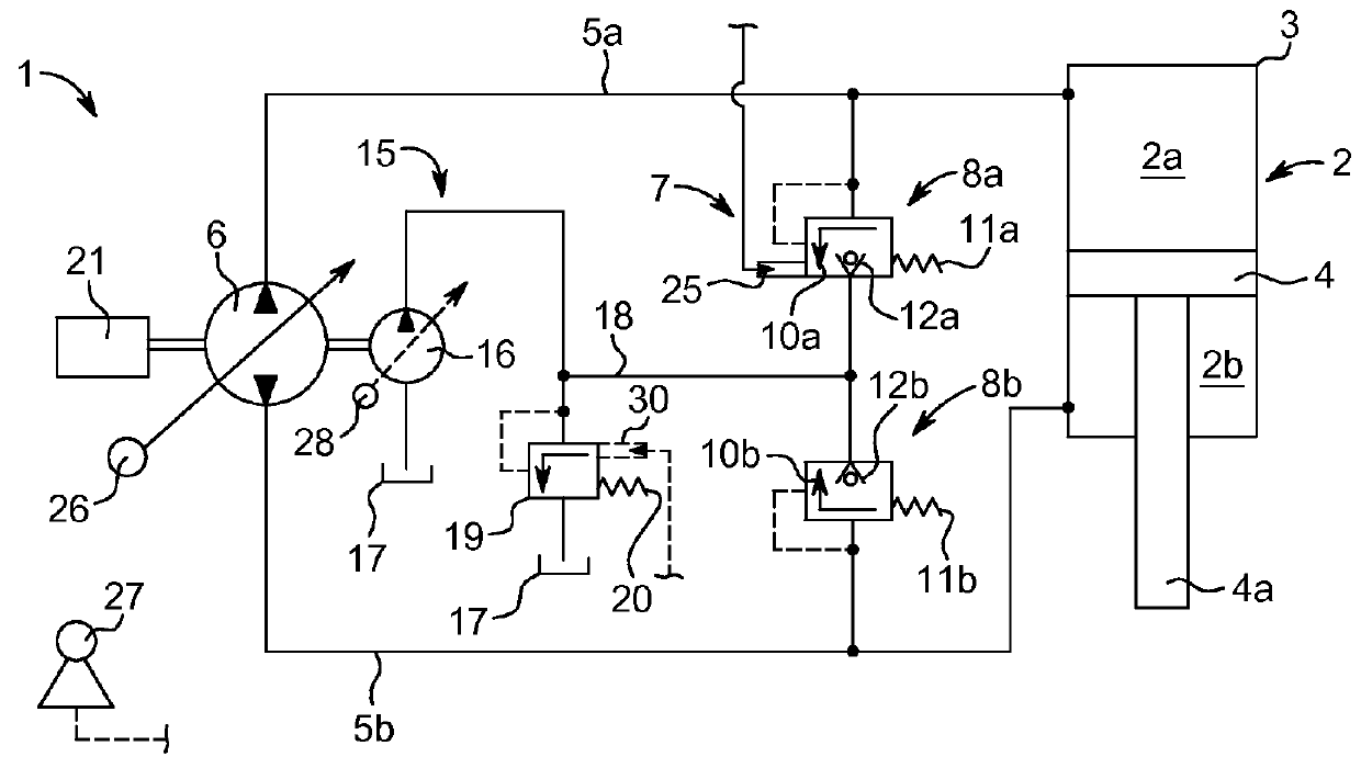
[0022]The accompanying FIGURE is a schematic diagram of a hydrostatic drive system 1 according to an embodiment of the invention. The drive system 1 comprises a differential cylinder 2 operated as a consumer in the closed circuit. The differential cylinder 2 includes a piston 4 which can be displaced longitudinally in a housing 3, whereby the piston 4 is provided on one side with a piston rod 4a.

[0023]The differential cylinder 2 has a piston-side compression chamber 2a which is connected by means of a first power fluid line 5a to a high-pressure pump 6, and a piston-rod-side compression chamber 2b which is connected by means of a second power fluid line 5b to the high-pressure pump 6. The compression chambers 2a, 2b of the differential cylinder 2 have different volumes on account of the piston rod 4a which is located in the piston-rod-side compression chamber 2b.

[0024]The closed circuit, which is formed by the power fluid lines 5a, 5b and which forms a high-pressure system, compri...


PUM


Abstract

A hydrostatic drive system includes a differential cylinder connected in a closed circuit to a high-pressure pump. A piston-side compression chamber and a piston-rod-side compression chamber of the differential cylinder are in communication with the high-pressure pump. The closed circuit includes a protection device having first and second protection valve devices that each includes a pressure relief valve and an anti-cavitation valve. The pressure relief valve of the first protection valve device is provided with an override device, by means of which the opening pressure of the pressure relief valve can be varied. When the high-pressure pump delivers into the piston-rod-side compression chamber, the pressure relief valve of the first protection valve device is adjusted by means of the override device to a reduced opening pressure and the differential volumetric flow flows out via the pressure relief valve to a low-pressure system.

Description

CROSS REFERENCE TO RELATED APPLICATION[0001]This application claims priority to German Application No. 10 2012 101 231.8 filed Feb. 16, 2012, which is herein incorporated by reference in its entirety.BACKGROUND OF THE INVENTION[0002]1. Field of the Invention[0003]This invention relates to a hydrostatic drive system with a user which is in the form of a differential cylinder and is connected in a closed circuit to a high-pressure pump. A piston-side compression chamber of the differential cylinder is in communication by means of a first power fluid line and a piston-rod-side compression chamber of the differential cylinder is in communication by means of a second power fluid line with the high-pressure pump. The closed circuit comprises a protection device which is formed by a first protection valve device that comprises a pressure relief valve and an anti-cavitation valve which is associated with the first power fluid line, and a second protection valve device which comprises a pres...

Claims


Application Information

Patent Timeline
Patent Type & Authority Patents(United States)
IPC IPC(8): F15B15/20F15B7/00
CPCF15B15/20F15B7/006F15B2211/20546F15B2211/20561F15B2211/27F15B2211/5059F15B2211/613
Inventor STUERMER, BURKHARDTOBIAS, HORST
Owner LINDE HYDRAULICS
Why Eureka
Try Eureka