Anamorphic objective lens

an objective lens and anamorphic technology, applied in the field of anamorphic objective lenses, can solve the problems of increasing the complexity of the optical surface shape, less acceptable, manufacturing cost, etc., and achieve the effects of reducing the degree of aberration correction, reducing the residual lateral chromatic aberration, and reducing the degree of aberration

Active Publication Date: 2016-05-17
TAYLOR-HOBSON
View PDF11 Cites 5 Cited by
  • Summary
  • Abstract
  • Description
  • Claims
  • Application Information

AI Technical Summary

Benefits of technology

[0013]An anamorphic objective lens comprising along an optical axis and in order from an object space to an image space at least a negative (−) power spherical first lens group, an anamorphic second lens group, a positive (+) power spherical third lens group and having an optical stop located before or after or preferably within the spherical third lens group. The anamorphic second lens group has at least one cylindrical surface in a first direction and at least a second cylindrical surface in a substantially perpendicular direction to the first direction to enable a high degree of aberration correction over the whole image, whereby the residual longitudinal chromatic aberration and the residual lateral chromatic aberration are substantially reduced. The negatively powered spherical first spherical lens group may provide focusing by movement of at least one of the lens elements contained therein and may exhibit low breathing in the focus range.
[0014]The anamorphic second lens group provides a squeeze of the field of view so that the focal lengths in the X and Y directions are different by a ratio of about two times which is typical for traditional anamorphic optical systems. The positively powered third lens group adjacent the image space delivers the radiation passing through the optical system on to the image sensor with nearly telecentric light paths and suitably high relative illumination, thereby increasing the efficiency of many electronic sensors.
[0024]The anamorphic objective lens provides low residual chromatic aberration, a traditional oval bokeh shape, and different depths of field in the vertical and horizontal azimuth directions of the field.

Problems solved by technology

Many of the less desired residual optical aberrations and characteristics of this arrangement were accepted by cinematographers with film based cameras but with the advent and adoption of electronic sensor based digital cameras some of them have become less acceptable.
Improving the optical aberrations and characteristics of anamorphic objective lenses of this arrangement may involve increasing optical surface shape complexity and hence manufacturing cost including adding aspherical and free-form shaped optical surfaces.

Method used


Image

  • Anamorphic objective lens
  • Anamorphic objective lens
  • Anamorphic objective lens

Examples


Embodiment Construction

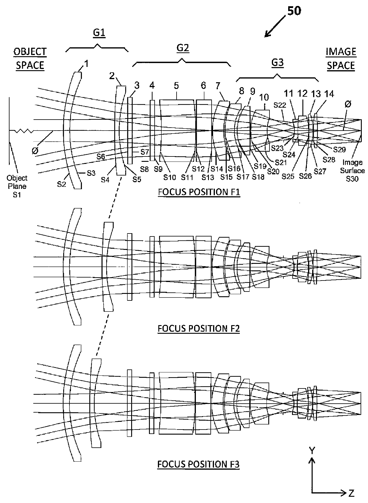
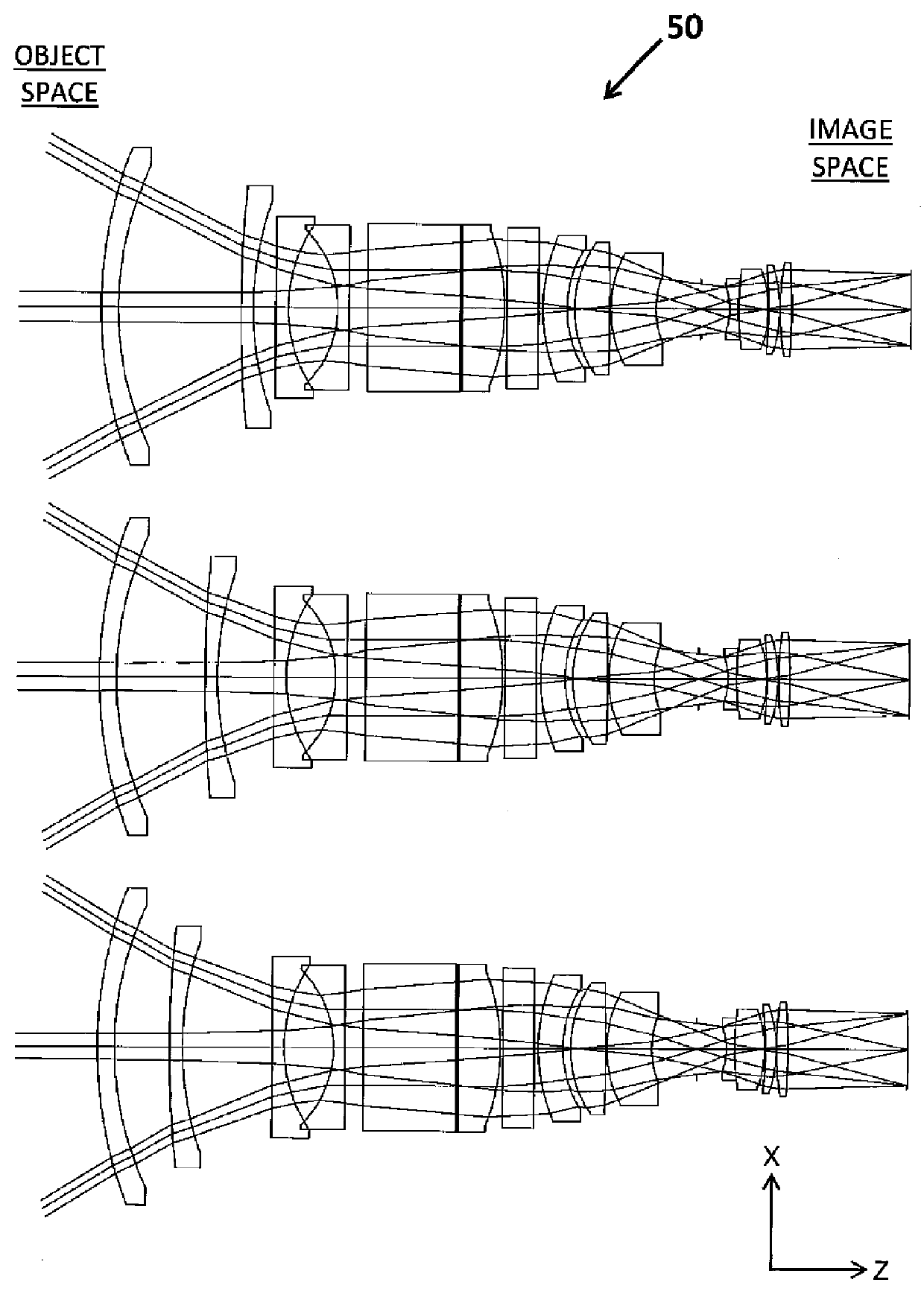
[0041]The invention relates to anamorphic objective lenses, and in particular to a range of different focal length anamorphic objective lenses covering at least a focal length range from 25 mm to 135 mm and providing low residual chromatic aberration, a traditional oval bokeh shape and different depths of field in the vertical and horizontal azimuth directions of the field.

[0042]The term “lens group” as used in connection with the anamorphic objective lens disclosed herein means one or more individual lens elements. Also, the terms “optical stop” and “stop” are equivalent terms that can be used interchangeably. A “field stop” as the term is used herein is a stop where the chief rays do not go through the center of the stop at the optical axis and the general purpose of a field stop is to vignette the edges of the radiation beams.

[0043]In the example provided herein, the front lens group is negatively powered and the rear lens group is positively powered and they have been paired wit...


PUM


Abstract

An anamorphic objective lens comprising, along an optical axis and in order from an object space to an image space: at least a negative (−) spherical first lens group; an anamorphic second lens group and a positive (+) spherical third lens group wherein an aperture stop is located before, after or preferably within the spherical third lens group. Both spherical lens groups contain spherical refractive optical surfaces and the anamorphic lens group contains cylindrical and plano optical surfaces with at least one cylindrical surface oriented at substantially 90 degrees about at least one other cylindrical surface. The negative spherical first lens group may provide focusing.

Description

CROSS-REFERENCE TO RELATED APPLICATIONS[0001]The present application claims the benefit under 37 CFR §119(e) of U.S. Provisional Application No. 61 / 808,343 filed Apr. 4, 2013, the contents of which are incorporated herein their entirety.STATEMENT REGARDING FEDERALLY SPONSORED RESEARCH OR DEVELOPMENT[0002]Not ApplicableREFERENCE TO A “SEQUENCE LISTING”, A TABLE, OR A COMPUTER PROGRAM LISTING APPENDIX SUBMITTED ON COMPACT DISC[0003]Not ApplicableBACKGROUND OF THE INVENTION[0004]1. Field of the Invention[0005]The present invention relates to anamorphic objective lenses, and more particularly to a range of different focal length anamorphic objective lenses providing traditional anamorphic imaging characteristics and having relatively simple optical surface shapes and corresponding potential minimized cost by having an arrangement of three lens groups with spherical, anamorphic and spherical powers and an optical stop located outside of the first and second lens groups.[0006]2. Descripti...

Claims


Application Information

Patent Timeline
Patent Type & Authority Patents(United States)
IPC IPC(8): G02B13/08G02B27/12G02B9/00G02B13/04G02B9/12G02B13/00G02B15/177G02B9/64G02B27/00
CPCG02B13/08G02B13/0045G02B13/04G02B27/0025G02B13/0015G02B9/64G02B15/177
Inventor NEIL, IAIN A.
Owner TAYLOR-HOBSON
Why Eureka
Try Eureka