Electrical switching apparatus, and indication assembly and trip cam therefor

a technology of switching apparatus and indication assembly, which is applied in the direction of switching side location, protective switch operating/release mechanism, and calibrating/seeing protective devices, etc., can solve the problems of occupying significant space within the circuit breaker and complex mechanisms

Active Publication Date: 2016-05-17
EATON INTELLIGENT POWER LIMITED
View PDF7 Cites 12 Cited by
  • Summary
  • Abstract
  • Description
  • Claims
  • Application Information

AI Technical Summary

Problems solved by technology

Such mechanisms are complex and take up si

Method used


Image

  • Electrical switching apparatus, and indication assembly and trip cam therefor
  • Electrical switching apparatus, and indication assembly and trip cam therefor
  • Electrical switching apparatus, and indication assembly and trip cam therefor

Examples


Embodiment Construction

[0028]As employed herein, the term “number” shall mean one or an integer greater than one (i.e., a plurality).

[0029]As employed herein, the statement that two or more parts are “connected” or “coupled” together shall mean that the parts are joined together either directly or joined through one or more intermediate parts.

[0030]As employed herein, the statement that two or more parts or components “engage” one another shall mean that the parts touch and / or exert a force against one another either directly or through one or more intermediate parts or components.

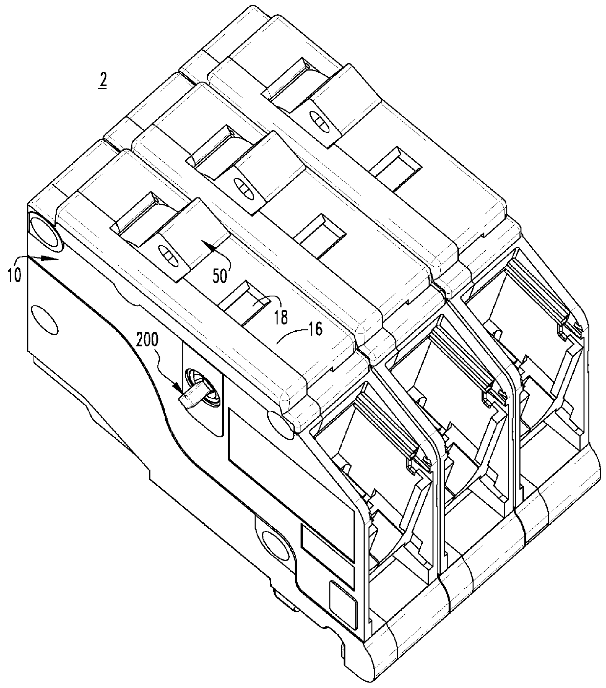
[0031]FIG. 1 shows an electrical switching apparatus (e.g., without limitation, circuit breaker 2) in accordance with the disclosed concept. The example circuit breaker 2 includes a housing 10, a number of operating handles (one operating handle 50 is indicated) extending into the housing 10, and a number of trip cams (only one trip cam 200 is partially visible in FIG. 1) located within the housing 10.

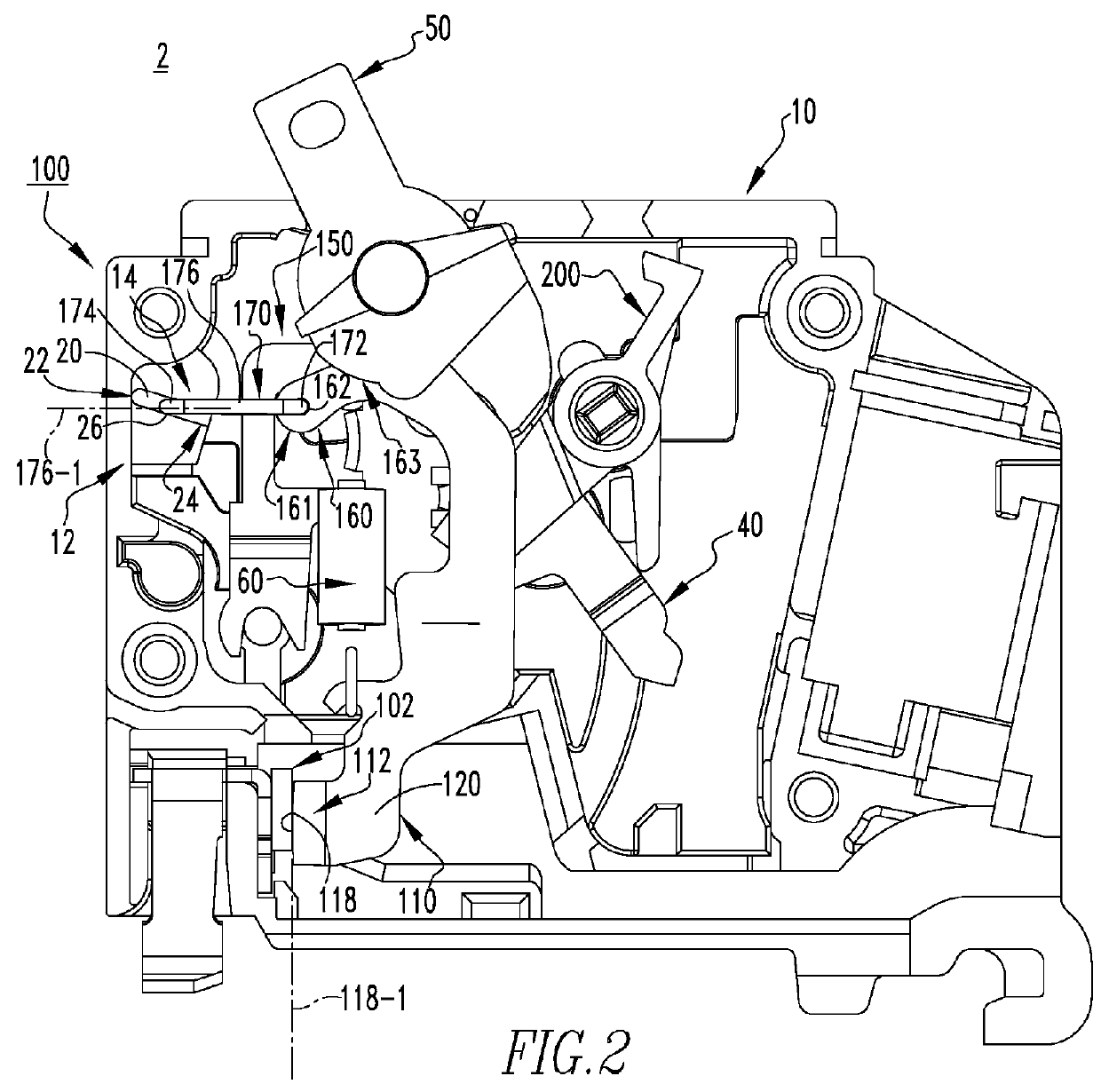
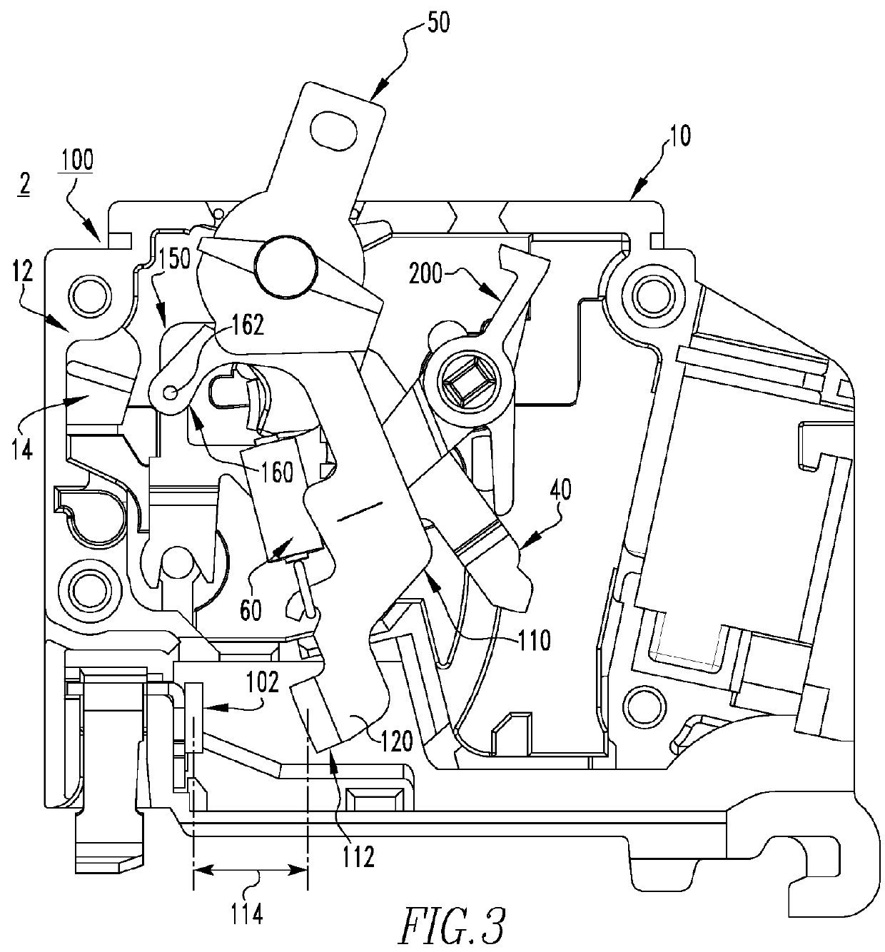
[0032]FIGS. 2 through 4 sho...


PUM


Abstract

A trip cam is for an indication assembly of an electrical switching apparatus. The electrical switching apparatus includes a housing and a number of poles. Each of the number of poles includes a pair of separable contacts and an operating mechanism structured to open and close the separable contacts. The indication assembly includes a cradle member. The trip cam includes: a mounting portion; a transfer leg extending from the mounting portion, the transfer leg being structured to cooperate with each of the number of poles; a driving leg extending from the mounting portion in a first direction, the driving leg being structured to be driven by the cradle member; and a trip indicator leg including a base portion. The base portion extends from the mounting portion in a second direction generally opposite the first direction.

Description

CROSS-REFERENCE TO RELATED APPLICATIONS[0001]This application is related to commonly assigned, concurrently filed[0002]U.S. patent application Ser. No. 14 / 558,921, filed, Dec. 3, 2014, and entitled “ELECTRICAL SWITCHING APPARATUS AND CONTACT ASSEMBLY THEREFOR”; and[0003]U.S. patent application Ser. No. 14 / 558,954, filed Dec. 3, 2014, and entitled “ELECTRICAL SWITCHING APPARATUS, AND OPERATING HANDLE ASSEMBLY AND TRIP CAM THEREFOR”.BACKGROUND[0004]1. Field[0005]The disclosed concept pertains generally to electrical switching apparatus such as for example, circuit breakers. The disclosed concept also pertains to indication assemblies for electrical switching apparatus. The disclosed concept further relates to trip cams for indication assemblies.[0006]2. Background Information[0007]Electrical apparatus, such as electrical switching apparatus or electrical meters used in power distribution systems, are often mounted on or within an electrical enclosure (e.g., without limitation, a panel...

Claims


Application Information

Patent Timeline
IPC IPC(8): H01H3/42H01H71/04H01H69/01
CPCH01H71/04H01H69/01H01H2223/00H01H2225/006H01H2069/016H01H71/505H01H71/522H01H21/22H01H71/50H01H71/52
Inventor GIBSON, JEFFREY SCOTT
Owner EATON INTELLIGENT POWER LIMITED
Why Eureka
Try Eureka