System and method for spinal deformity correction

a spinal deformity and system technology, applied in the field of spinal deformity correction, can solve the problems of cumbersome use, ineffective conventional systems and methods, and difficult us

Active Publication Date: 2016-05-31
SHARPS CHESTER H
View PDF9 Cites 3 Cited by
  • Summary
  • Abstract
  • Description
  • Claims
  • Application Information

AI Technical Summary

Problems solved by technology

Typically, conventional systems and methods have been ineffective, cumbersome, and difficult to use.

Method used


Image

  • System and method for spinal deformity correction
  • System and method for spinal deformity correction
  • System and method for spinal deformity correction

Examples


Embodiment Construction

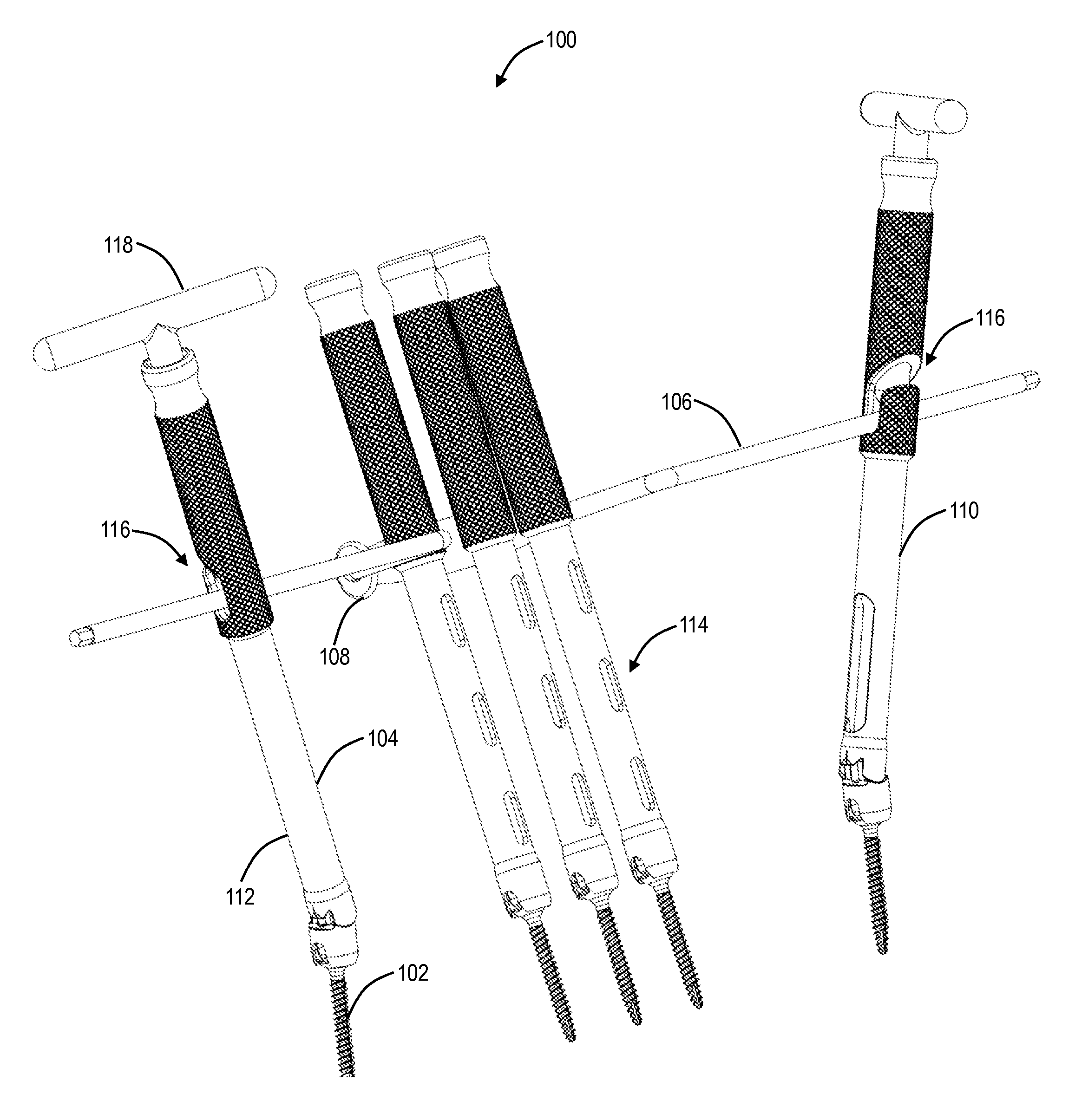
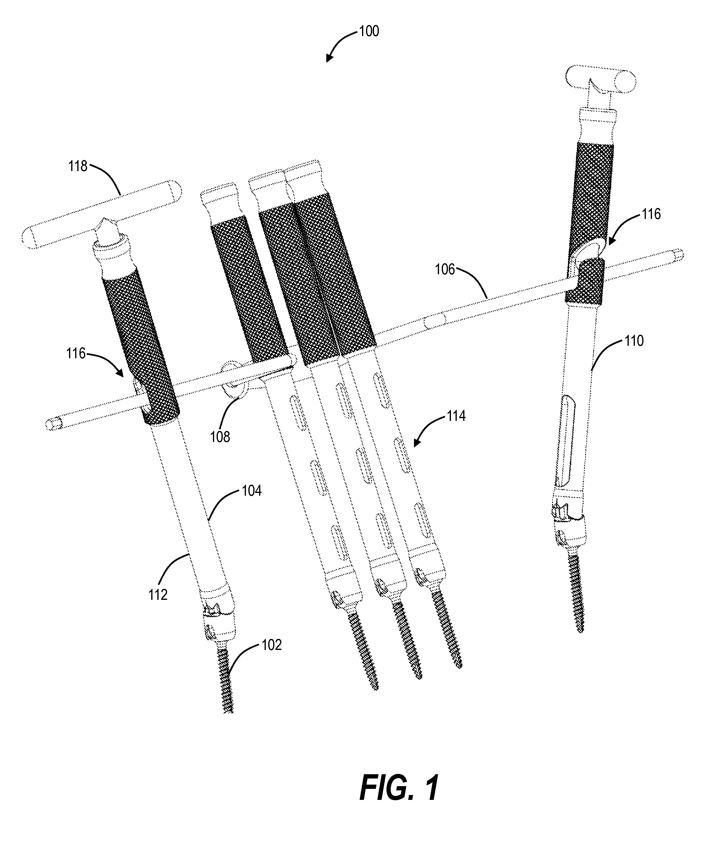
[0027]Referring now specifically to FIG. 1, in one exemplary embodiment, the spinal deformity correction system 100 of the present invention facilitates the correction of a spinal deformity, such as scoliosis, and may, more specifically, be used to derotate a spine in which one or more vertebrae are rotated axially at an angle that is not aligned with the patient's sagittal plane, i.e. the system 100 may be used to derotate vertebrae that are out of sagittal alignment. The spine may have a treatment region including a cephalad vertebra and a caudal vertebra. The cephalad vertebra is at the cephalad end of the treatment region (i.e. the end nearest the head of the patient) and the caudal vertebra is at the caudal end of the treatment region (i.e. the end furthest from the head of the patient). The spine also has one or more intermediate vertebrae disposed between the cephalad vertebra and the caudal vertebra. The cephalad vertebra and the caudal vertebra may be in proper sagittal ali...


PUM


Abstract

A system and associated surgical method for the correction of a spinal deformity by derotating one or more vertebrae of the spine, including: a rotation rod; a cephalad extender configured to be rotatably coupled to the rotation rod and coupled to a cephalad vertebra; a caudal extender configured to be rotatably coupled to the rotation rod and coupled to a caudal vertebra; and one or more intermediate extenders configured to be coupled to one or more intermediate vertebrae; wherein, when the rotation rod is rotated, a portion of the rotation rod engages a portion of the one or more intermediate extenders, causing the one or more intermediate extenders to rotate about an axis of the spine, thereby causing the one or more intermediate vertebrae to also rotate about the axis. The extenders are each coupled to their respective vertebra via a pedicle screw or the like.

Description

CROSS-REFERENCE TO RELATED APPLICATION[0001]The present patent application / patent claims the benefit of priority of U.S. Provisional Patent Application No. 61 / 877,321, filed on Sep. 13, 2013, and entitled “SYSTEM AND METHOD FOR SPINAL DEFORMITY CORRECTION,” the contents of which are incorporated in full by reference herein.FIELD OF THE INVENTION[0002]The present invention relates generally to the medical and spinal surgery fields. More specifically, the present invention relates to a system and method for spinal deformity correction.BACKGROUND OF THE INVENTION[0003]A number of conventional systems and methods exist for the correction of spinal deformities, such as scoliosis. In general, these systems and methods are used to “derotate” the spine when one or more vertebrae are rotated axially at an angle that is not aligned with the patient's sagittal plane. Once the spine is derotated (or simultaneous with derotation), pedicle screws and rods or the like are placed and secured to mai...

Claims


Application Information

Patent Timeline
Patent Type & Authority Patents(United States)
IPC IPC(8): A61B17/70A61B17/88
CPCA61B17/708A61B17/7032A61B17/8875
Inventor SHARPS, CHESTER H.
Owner SHARPS CHESTER H
Why Eureka
Try Eureka