
Spinal Deformity Correction Device

A technology of spinal deformity and arc-shaped slices, which is applied in the field of spinal deformity correction devices, can solve the problems of reducing the correction accuracy, not being able to put one part in place, and affecting the correction of the spine, achieving intensive, convenient and fast operation, enhanced accuracy and convenience sexual effect

Inactive Publication Date: 2018-06-15
HENAN UNIV OF CHINESE MEDICINE
View PDF7 Cites 0 Cited by
  • Summary
  • Abstract
  • Description
  • Claims
  • Application Information

AI Technical Summary

Problems solved by technology

[0003] The device for correcting the spine in the prior art is to fix the posterior spinal screw connector on a device that can be lifted horizontally, vertically and up and down. Different places adjust the horizontal, vertical and up-and-down lifts separately. The doctor needs to move back and forth to control the spine when correcting the spine, so that the doctor cannot keep staring at the spine for adjustment during the adjustment process, which affects the quality of correction. And in the correction process The horizontal and vertical movements cannot be carried out at the same time, and the horizontal and vertical movements need to be carried out separately to achieve the desired position. One part cannot be in place, which affects the correction of the spine. Sometimes it needs to be adjusted back and forth, which increases the length of operation time and reduces the accuracy of correction.

Method used


Image

  • Spinal Deformity Correction Device
  • Spinal Deformity Correction Device
  • Spinal Deformity Correction Device

Examples


Embodiment Construction

[0013] The specific implementation manners of the present invention will be described in further detail below in conjunction with the accompanying drawings.

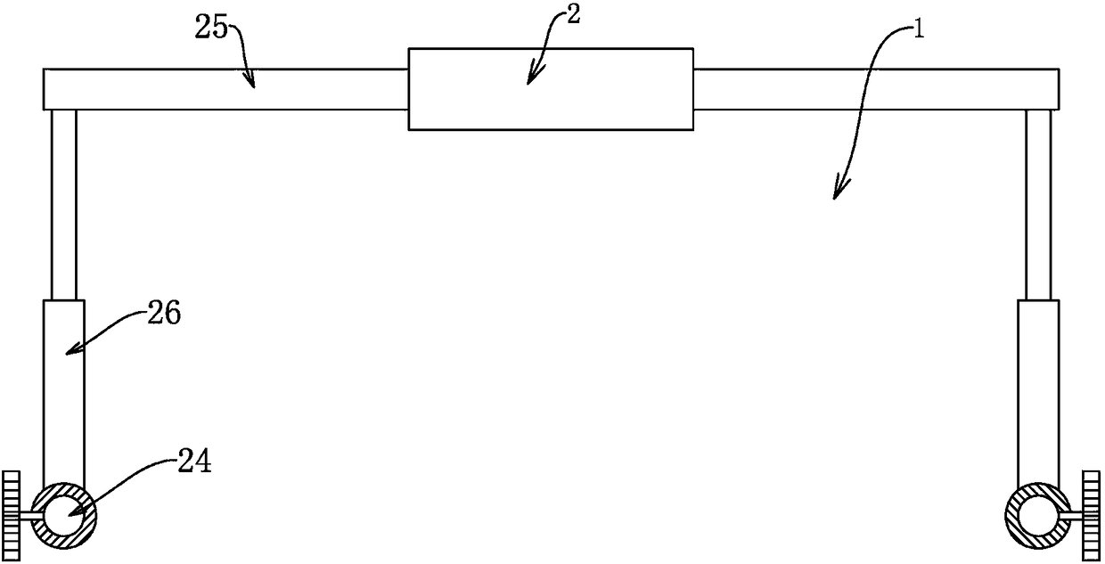
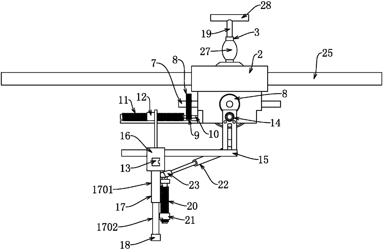
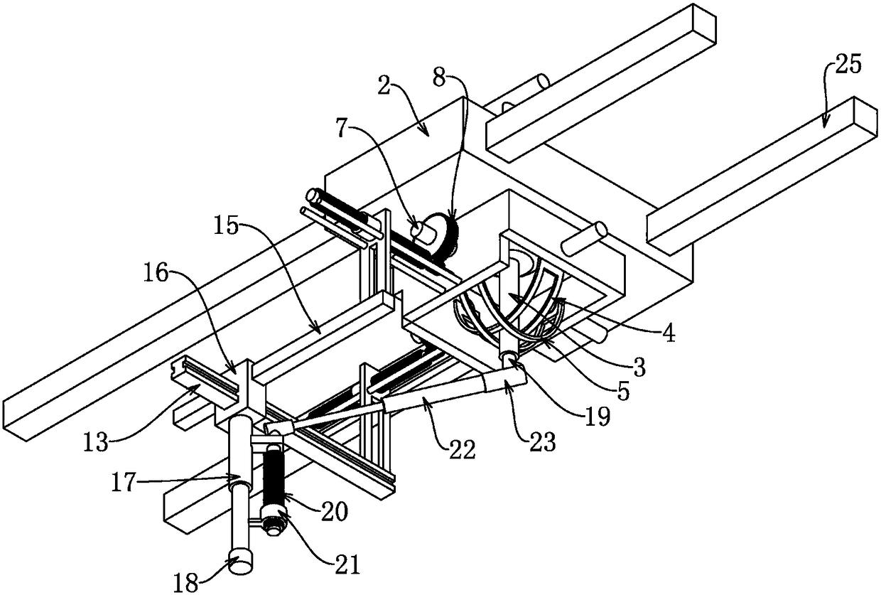
[0014] Depend on Figure 1 to Figure 6 Given, the technical solution of the present invention is to include an operating bed fixing frame 1 that can be slid up and down along the length direction of the operating bed, and the upper end of the operating bed fixing frame 1 is slidingly provided with a base 2 along the width direction of the operating bed , it is characterized in that the inner ball of the base 2 is hinged with a vertical joystick 3, and the first arc-shaped piece 4 and the second arc-shaped piece 4 and the second arc-shaped piece 4 that are staggered and rotated on the base 2 are arranged under the base 2 The arc-shaped sheet 5, the first arc-shaped sheet 4 and the second arc-shaped sheet 5 are respectively provided with upward and downward transparent sliding holes 6 extending along the arc-shaped directi...


PUM


Abstract

The invention provides a spinal deformity correction device. The invention can simultaneously manipulate the posterior spinal screw connector to move at any angle in the horizontal position through the action of the joystick. When tilting movement is required, separate horizontal and vertical movements are not required to achieve tilting movement The purpose is achieved, and the wrist is easier to control the joystick than the arm. When the joystick moves to the specified position, it can move somewhere in the spine through the precise control of the translation screw, and can be positioned at the current position in real time. The lifting of the spine is realized by driving the lifting screw through the lifting rod, which can be positioned in real time. Whether it is lifting or moving horizontally, it is all operated at the same place. The intensive operation greatly facilitates the doctor's quick operation. The spine can be moved at any angle by direct movement of the hand, which greatly enhances the accuracy and convenience of spine movement.

Description

technical field [0001] The invention relates to a spinal deformity correction device. Background technique [0002] Spinal deformity is a common and frequently-occurring disease, which is caused by many reasons, and can be single or multiple coexistence, manifested as scoliosis, rotation, anterior or kyphotic deformity, stiffness, etc. It can occur in all age groups, especially For children and teenagers, it not only affects the appearance, but more importantly, it is very easy to threaten the functions of the heart, lungs, and nervous system, seriously endangering people's physical and mental health. A large proportion of patients require surgery to correct the deformity. [0003] The device for correcting the spine in the prior art is to fix the posterior spinal screw connector on a device that can be lifted horizontally, vertically and up and down. Different places adjust the horizontal, vertical and up-and-down lifts separately. The doctor needs to move back and forth ...

Claims


Application Information

Patent Timeline
Patent Type & Authority Patents(China)
IPC IPC(8): A61G13/00A61G13/10
Inventor 岳宗进于露刘汝银彭晓艳鲁花冯仲锴王新立王西彬李云朋许大勇
Owner HENAN UNIV OF CHINESE MEDICINE
Learn More