Anchoring device for use in spinal deformity correction surgery

a technology for spinal deformation and anchoring, which is applied in the direction of osteosythesis devices, internal osteosythesis, bone plates, etc., can solve the problems of significant weakening of the rigid spinal structure created, the failure of the bone-screw interface, and the disadvantages of using pedicle screws

Pending Publication Date: 2022-10-06
DODDS MICHAEL KENNETH
View PDF0 Cites 0 Cited by
  • Summary
  • Abstract
  • Description
  • Claims
  • Application Information

AI Technical Summary

Problems solved by technology

However, the use of pedicle screws comes with some disadvantages, especially in the context of being attached directly to a stabilising rod.
One fundamental weakness of screws is that the bone-screw interface can sometimes fail in response to excessive axial pull-out forces.
This phenomenon may be commonly encountered in scoliosis surgery in particular, and it may significantly weaken the rigid spinal construct created as a means of treating it.
This can sometimes be a particularly significant issue at the concavity of the apex of the scoliotic curve, owing to both the abnormal anatomy of the vertebrae in this region of the spine and also the greater translative distance the spine has to travel in being drawn onto a stabilising rod in this region.
Sub-laminar bands or tapes are better able to resist axial pull-out forces than screws, although they may have a limited ability to transfer torsional forces to the spine and to derotate deformities.
However, such an anchoring device has limited usefulness in practice, owing to its configuration and reliance on the conventional rod-locking screw/nut to anchor the collar-like cap onto the screw head.
Indeed, the design and function of such known band/

Method used


Image

  • Anchoring device for use in spinal deformity correction surgery
  • Anchoring device for use in spinal deformity correction surgery
  • Anchoring device for use in spinal deformity correction surgery

Examples


Embodiment Construction

[0126]In the accompanying drawings, any specific dimensions (e.g. in mm or cm) that may be annotated thereon are to be considered to be non-limiting and for purely illustrative example purposes only.

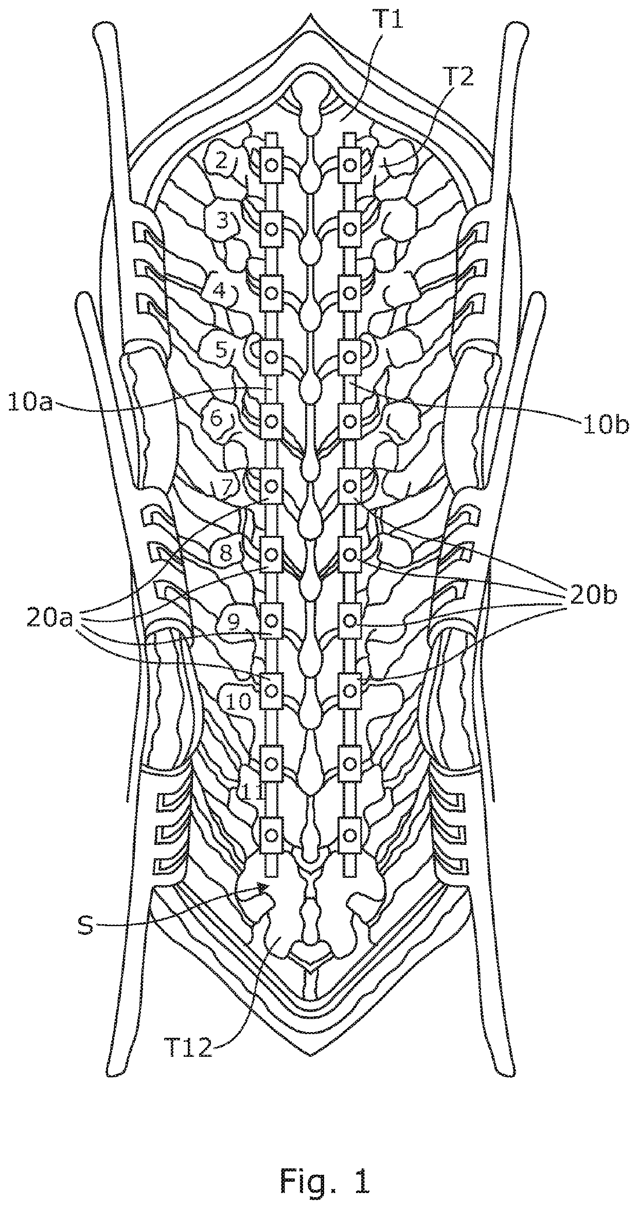
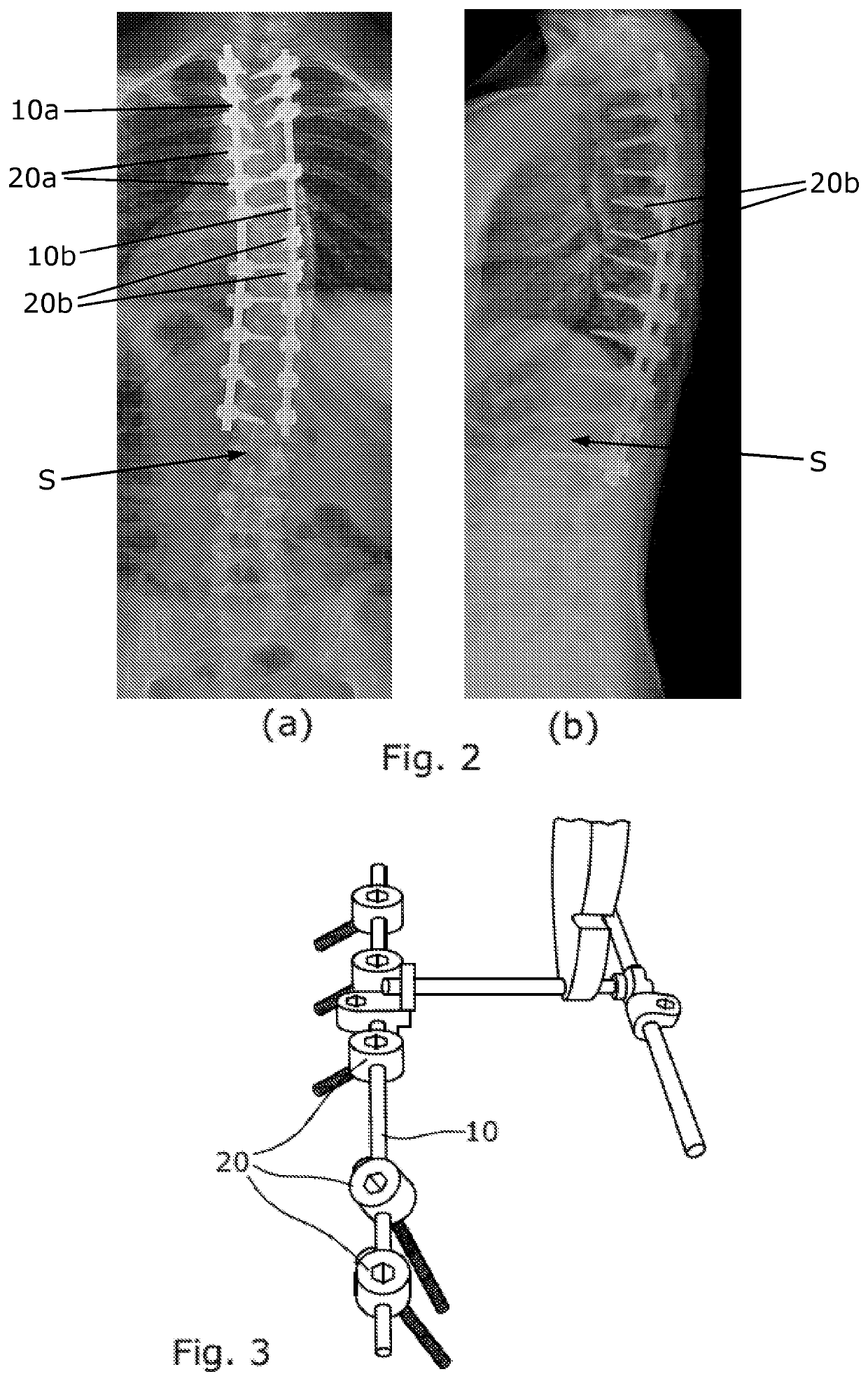
[0127]Referring firstly to FIG. 1, this shows purely by way of an illustrative example a human spinal region, in posterior view, which has been exposed during spinal deformity corrective surgery to mount a pair of substantially rigid constructs or assemblies onto the various thoracic vertebrae (labelled conventionally as T1-T12) for the purpose of correcting a spinal deformity such as that caused by scoliosis. In this example, a pair of generally parallel stabilising rods 10a, 10b have been mounted on and secured to a respective series of screws 20a, 20b each of which has been inserted into the bone of a respective pedicle or other part of the relevant vertebra of the spinal column S. FIGS. 2(a) and (b) show the overall spinal implant arrangement more clearly in three dimensions in the f...


PUM


Abstract

An anchoring device (40) for anchoring one or more sub-laminar bands or tapes (60a, 60b) to a pedicle screw (30), the device (40) comprising: a first portion (41) configured for attachment to at least a base portion (32 L) of a head portion (32) of the pedicle screw (32); and at least one second portion (46a, 46b) for anchoring thereto a or a respective sub-laminar band or tape (60a, 60b); wherein the first portion (41) includes first interengagement means (42Na, 42 Nb) for interengagement with corresponding notches or recesses (32Na, 32 Nb) in the head portion (32) of the pedicle screw (32) to effect the said attachment of the first portion (41) of the anchoring device (40) thereto.

Description

TECHNICAL FIELD[0001]This invention relates to an anchoring device for use in spinal deformity correction surgery. More particularly, though not exclusively, the invention relates to an anchoring device for use with a pedicle screw, especially by attachment to a pedicle screw, to provide a system for enhanced anchoring of sub-laminar bands used in corrective spinal vertebral fixation surgery. The invention further relates to such anchoring device and pedicle screw combinations, to a pedicle screw for use with such an anchoring device, and to methods of use of such anchoring devices and anchoring device-and-pedicle screw combinations in spinal deformity correction surgery.BACKGROUND OF THE INVENTION AND PRIOR ART[0002]Scoliosis is a common form of spinal deformity. Surgical correction of the deformity generally involves the implantation of fixation anchors onto plural vertebrae, which are then drawn onto a stabilising rod, resulting in partial correction of the deformity and the rigi...

Claims


Application Information

Patent Timeline
IPC IPC(8): A61B17/70A61B17/80
CPCA61B17/7022A61B17/7034A61B17/7044A61B17/7053A61B17/707A61B17/8047A61B17/7032A61B17/7002
Inventor DODDS, MICHAEL KENNETH
Owner DODDS MICHAEL KENNETH
Why Eureka
Try Eureka