Method for operating a motor vehicle during and/or following a collision

a technology for motor vehicles and collisions, applied in the direction of pedestrian/occupant safety arrangements, instruments, tractors, etc., can solve the problems of increasing the severity of subsequent collisions, other problems may arise, and systems cannot be triggered

Active Publication Date: 2016-05-31
AUDI AG
View PDF29 Cites 152 Cited by
  • Summary
  • Abstract
  • Description
  • Claims
  • Application Information

AI Technical Summary

Benefits of technology

[0028]In addition to the method, the present invention also relates to a motor vehicle, with at least one control device designed for implementing the method according to the invention. All embodiments with respect to the inventive method can be applied analogously to the motor vehicle according to the invention, which thus provides the same advantages. In particular the motor vehicle includes at least one on-board electrical system, which is powered by at least one electrical energy source, in particular by at least one battery. The on-board electrical system supplies several vehicle systems of the motor vehicle. The supply of power to certain vehicle systems, optionally at least partly also to groups of vehicle systems, can be controlled via a corresponding switching device. This switching device is then controlled by the control device that controls the method of the invention, so as to deenergize the vehicle systems step-by-step based on the criteria.

Problems solved by technology

When a collision is inevitable, i.e. when the dynamic possibilities of the motor vehicle through driving interventions are no longer adequate to avoid a collision with a collision partner, then other problems may arise after the initial collision, for example, consequential collisions.
In this way, however, the safety systems of the motor vehicle are also deenergized, so that the safety systems can no longer be triggered again, in particular following a first accident, i.e. the collision.
This increases the severity of subsequent collisions, since accident-severity-mitigating measures for a subsequent collision can no longer be initiated after the first collision.

Method used


Image

  • Method for operating a motor vehicle during and/or following a collision
  • Method for operating a motor vehicle during and/or following a collision

Examples


Embodiment Construction

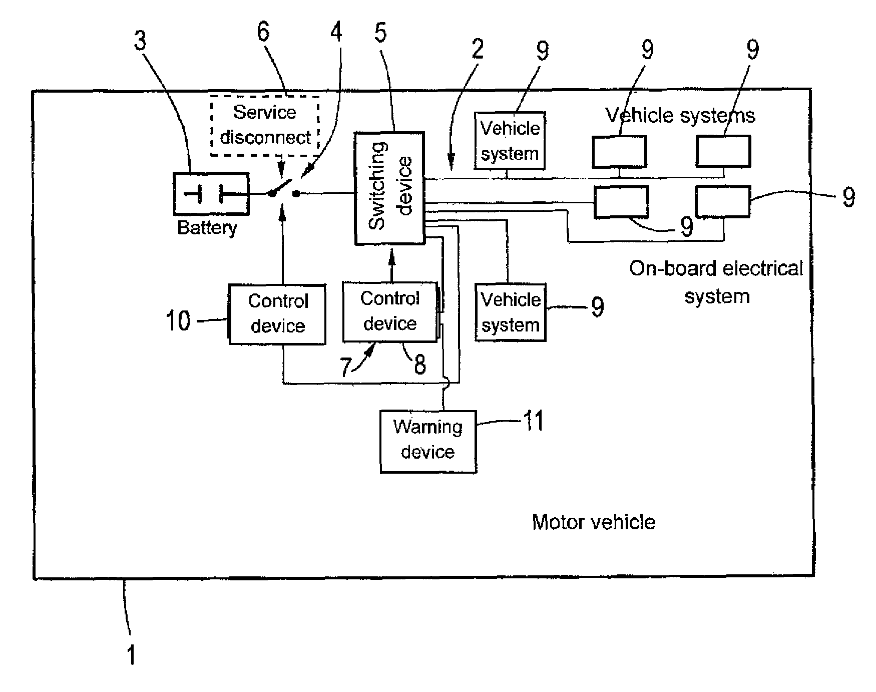
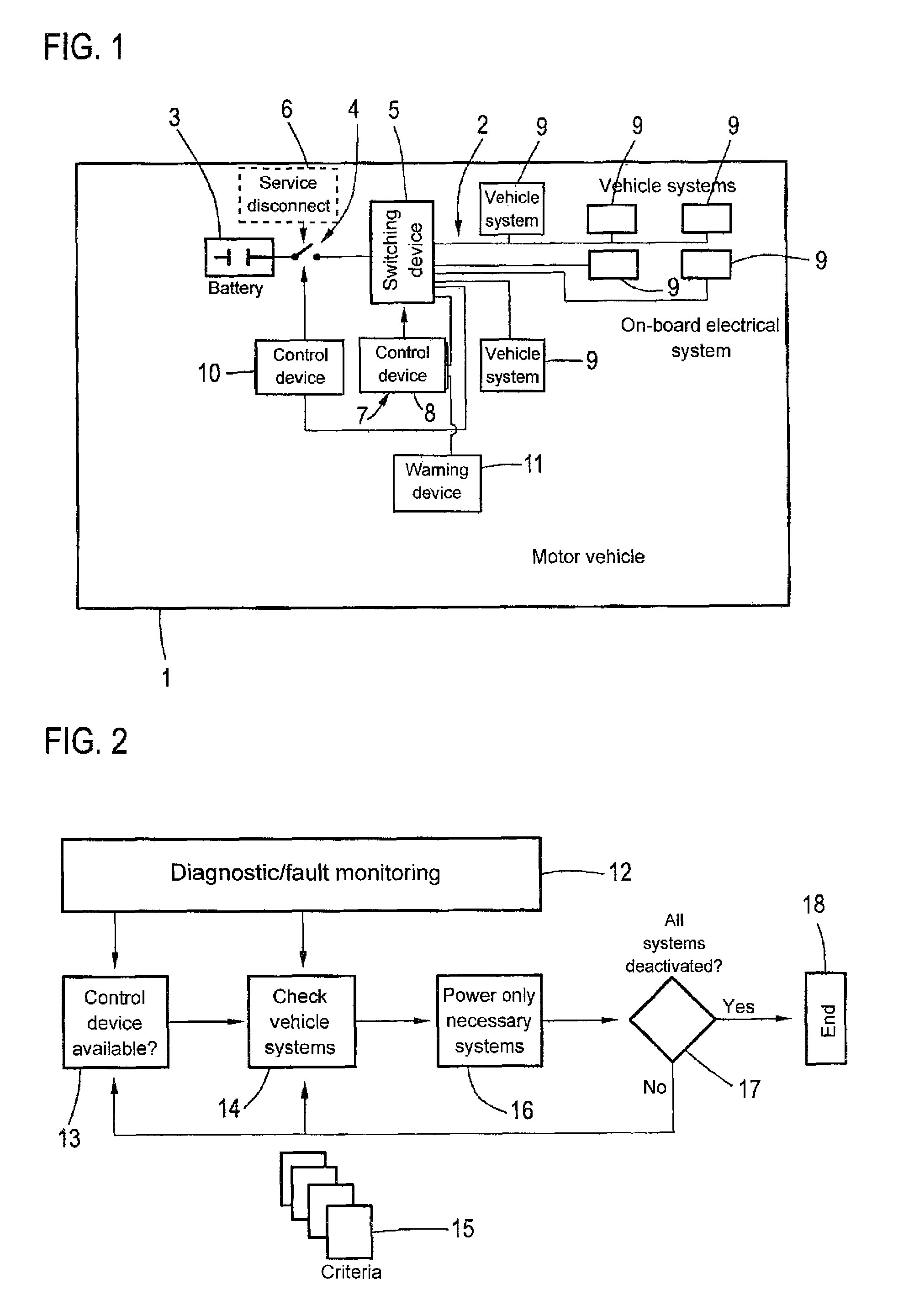
[0032]FIG. 1 shows a schematic diagram of a motor vehicle 1 according to the invention. The motor vehicle 1 has, as is generally known, an on-board electrical system 2 for supplying power to various vehicle systems of the motor vehicle 1. The on-board electrical system 2 is energized by an electrical power source, here a battery 3. A main switch 4 and a switching device 5 thereby determine, which vehicle system is to be supplied with electrical energy, wherein with respect to the main switch 4 a service disconnect device 6 can enable a complete disconnection of the battery 3 from the on-board electrical system 2. A vehicle system includes a battery management system 7 with a control device 8, which is configured to carry out the method according to the invention, which the following description will address in more detail.

[0033]The method according to the invention relates to the operation of the motor vehicle 1, in particular with regard to the electric power supply, in a time peri...


PUM


Abstract

A method for operating a motor vehicle (1), particularly the supply of power to a motor vehicle (1), during and/or in the time period following a collision, wherein the motor vehicle (1) is at least partially deenergized, wherein the supply of electrical power of a vehicle system (9) is determined and switched during and/or following the collision based on at least one criterion (15).

Description

CROSS-REFERENCES TO RELATED APPLICATIONS[0001]This application is the U.S. National Stage of International Application No. PCT / EP2013 / 00969, filed Apr. 2, 2013, which designated the United States and has been published as International Publication No. WO 2013 / 149720 and which claims the priority of German Patent Application, Serial No. 10 2012 007 119.1, filed Apr. 5, 2012, pursuant to 35 U.S.C. 119(a)-(d).BACKGROUND OF THE INVENTION[0002]The invention relates to a method for operating a motor vehicle, in particular the supply of power of a motor vehicle, during a collision and / or during a time period following a collision, wherein the motor vehicle is at least partially deenergized. In addition, the invention relates to a motor vehicle with at least one control device configured to carry out the method.[0003]Active and passive safety systems, which are designed in particular for collision avoidance and / or collision mitigation, are already known in the prior art. For example, such s...

Claims


Application Information

Patent Timeline
Patent Type & Authority Patents(United States)
IPC IPC(8): G01M17/00B60R21/01B60R21/00B60W50/029B60R16/03G07C5/00B60K28/00
CPCB60R16/03B60R21/00B60R21/01B60W50/029G07C5/00B60K2028/006B60R2021/01252B60W2050/0295
Inventor BRENNEIS, OLIVERFREYER, JORNHANTSCHKE, CHRISTOPHER
Owner AUDI AG
Why Eureka
Try Eureka